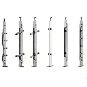
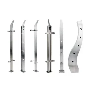
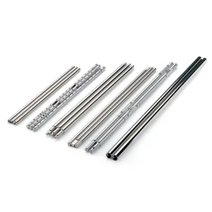
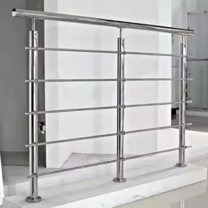
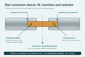
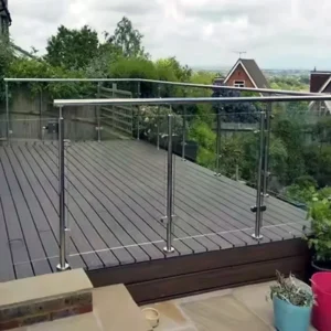
Adjustable post-base hardware is used when the receiving tube or post angle cannot be fixed as a simple 90-degree connection. The first question is what must adjust: a pivot angle, post plumb, height, or only installation tolerance. These functions use different parts and locking methods. Send the post profile, required final angle or range, mounting-face information and quantity so ESANG can identify a proposed configuration.
Ask about adjustable base hardware on WhatsApp
Specify the adjustment that the joint must make
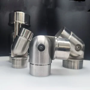
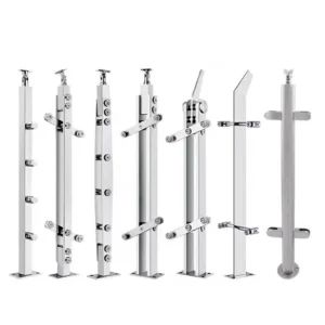
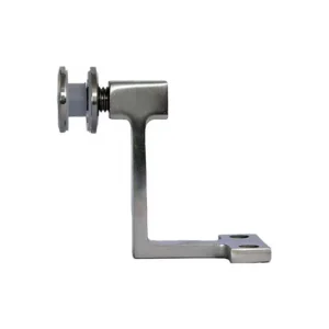
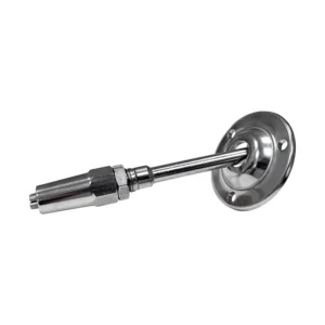
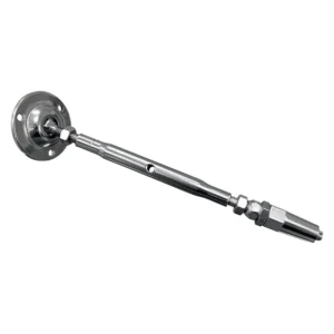
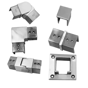
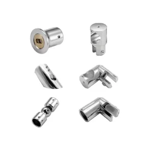
The public product images show a pivoting tube receiver over a lower mounting body. That visible form supports a discussion about setting an angle at the receiver-to-base joint; it does not establish a leveling plate, a height-adjustable anchor, or a joint intended to move during service.
- Pivot direction: show the plane in which the receiver must rotate and the final installed angle. A joint that pivots in one plane may not correct a compound slope.
- Adjustment stage: state whether the angle is set during factory assembly or aligned on site before final tightening. Do not assume the joint remains adjustable after the railing is loaded.
- Locking and retention: request the proposed pin, screw, clamp, thread or other retention detail, access for tightening, and any required locking procedure.
- Post interface: provide the tube outside diameter or profile, wall thickness, insertion depth requirement and any holes, welds or set-screw positions that must be coordinated.

The base-side connection remains a separate design
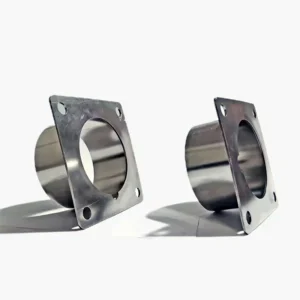
A pivoting receiver does not determine how the lower body attaches to the building. The proposed part may connect to a separate surface plate, threaded insert, welded assembly or another designed component. The quotation must show that lower interface and identify which items are included. If a plate and anchors are separate, their hole pattern, material and installation specification should be listed separately.
The completed load path includes the post, adjustable joint, locking hardware, lower body, any structural plate, anchors or welds, and the supporting substrate. The project designer or responsible engineer approves the design actions and complete connection. Product naming or an angled product photograph is not evidence of a load capacity or approval for stairs, guards, ramps or a particular substrate.
Adjustment is not a remedy for unsuitable site geometry
Before relying on an adjustable joint, check whether the mounting face itself is flat and structurally suitable. A joint may correct a post or tube angle, but it does not create anchor edge distance, repair weak concrete, replace timber blocking, bridge a waterproofing build-up or remove the need for a verified bearing surface.
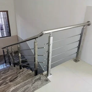
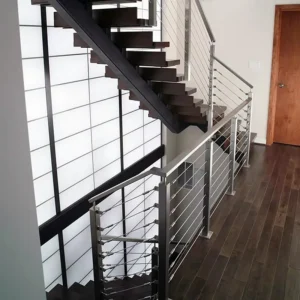
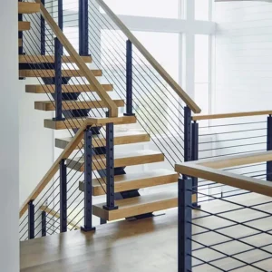
For a stair or sloped run, provide a section through the tread, slab or stringer. Mark the finished slope, required post line, handrail or top-rail line, nearby edges and any interference with tightening tools. If several angles occur, list quantities by angle instead of requesting one "universal" part.
Freeze the joint before production
The reviewed drawing or quotation should state:
- upper receiver profile, outside size and insertion or attachment detail;
- lower body interface and any separate plate, insert or weld preparation;
- adjustment plane and proposed working range, with the required final setting;
- pivot and locking components, tightening access and assembly sequence;
- material and visible finish proposed for each exposed component;
- included fasteners and any anchors or site hardware expressly excluded;
- drawing revision, quantity by configuration and inspection documents requested.
Where a mock-up is required, define what it must demonstrate: physical fit and adjustment, appearance, installation access, or a separately specified performance test. A fit sample alone does not verify structural capacity.
Information needed to quote
An initial request can begin with a photo, approximate quantity and target angle. To release the part, add the post or tube drawing, lower mounting detail, exact final angles, left/right orientation where relevant, required finish, exposure, locking access and the project engineer’s connection criteria. ESANG’s response should identify the proposed configuration rather than imply compatibility with every post or base.