Drilled glass does not forgive upstream layout errors. When spigot centerlines are treated as a fabrication detail rather than a planning decision, the misalignment they produce arrives on site already locked into the glass — and no amount of hardware adjustment recovers a hole pattern that doesn’t match the installed post positions. The practical cost is replacement of drilled panels, schedule delay, and the compounding frustration of a run that looks out of plane even when every individual component is within its own tolerance. What prevents that outcome is resolving centerlines, edge distances, panel sequence, and drawing content before fabrication releases — not after glass is ordered.
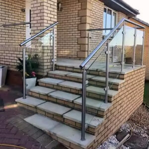
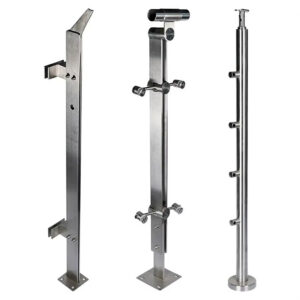
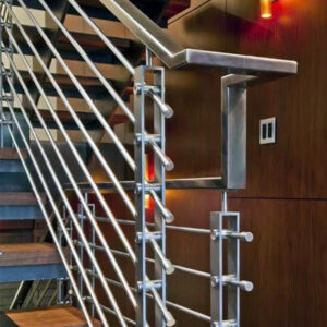
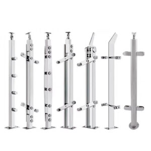
Spigot placement defines the installer leveling path
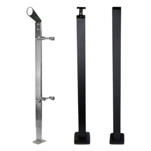
Spigot placement is a sequencing decision, not a hardware selection decision. Before any post gets set, the installer needs a clear leveling path: a defined start point, a known panel width, confirmed edge distances, and predictable gaps at corners and terminations. When those parameters exist on the layout drawing, the installer can work efficiently down the run. When they don’t, each panel becomes an independent problem to solve on site, and the time lost to repeated adjustment compounds across every subsequent position.
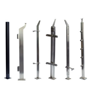
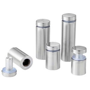
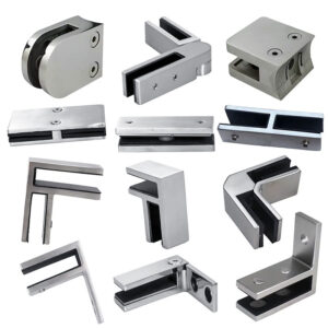
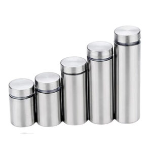
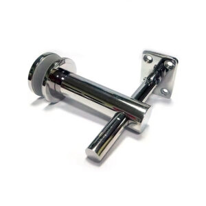
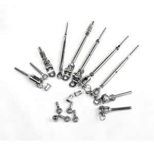
Two-way fixing and standoff adjustability in spigot hardware support this by giving the installer a limited correction window during leveling. That adjustability is not a substitute for a planned layout — its value is absorbing the small positional deviations that remain after careful setting, not compensating for a layout that was never resolved. Treating adjustability as a planning backstop rather than a tolerance buffer is a recurring mistake pattern on longer runs: teams assume the hardware will correct whatever the drawing left unresolved, and find during installation that the adjustment range runs out well before the panels align.
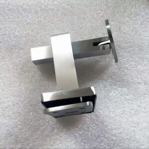
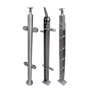
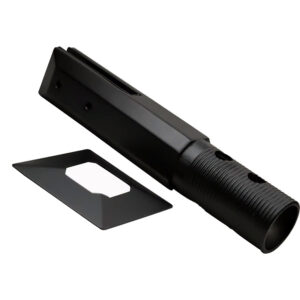
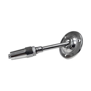
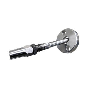
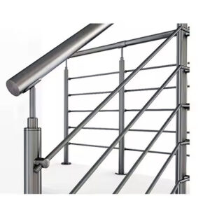
Embouts en verre pour montage en surface designed with two-way fixing allow incremental alignment correction during leveling, but that window is most effective when the spigot centerlines have already been set accurately on the drawing.
Centerlines, edge distances and panel sequence
Centerline spacing and panel width are interdependent. The panel width drives the centerline-to-centerline distance between spigots, and both are constrained by thresholds that vary with glass type, substrate, and applicable code conditions. Under IBC guardrail load conditions, post spacing is typically held to a 6-foot maximum; panel widths are generally kept to 4 feet or less, with the precise limit shaped by glass specification and the governing code for the project location. Neither figure is universal across all installation contexts, but together they define the outer bounds of the layout grid before panel sequence begins.
Panel sequence decisions flow from these thresholds. Once the maximum centerline spacing is established, the panel count across a run is essentially determined, and any corner or termination condition that doesn’t divide evenly into that module creates an end panel that needs its own edge distance calculation. Leaving that calculation to the installer means it gets resolved in the field, often by splitting a gap visually rather than dimensionally — which introduces inconsistency at the most visible part of the run.
| Paramètres | Maximum Allowable Limit | Governing Factor |
|---|---|---|
| Glass panel width | 4 pieds | Glass type and applicable building code |
| Post (spigot) spacing | 6 pieds | IBC guardrail load (200 lb) |
Adding spigots to satisfy the spacing limit improves load distribution but increases layout labor, adds visible hardware positions, and multiplies the number of points that must each land within acceptable field tolerance. That trade-off is worth acknowledging in the drawing review stage, not discovering during installation.
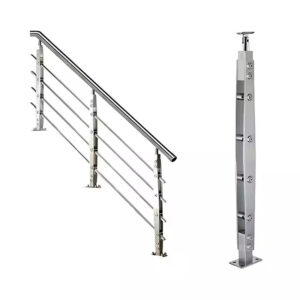
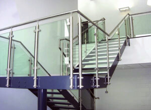
Field tolerance across a long post-mounted run
A single base-plate position that is off by a fraction of an inch may be correctable at that post. Across a long run, the same variance at every post accumulates into a cumulative offset that exceeds what spigot adjustability can absorb. This is the core alignment risk in extended post-mounted runs: small deviations don’t cancel out, they stack.
Field measurements for custom glass panels should be taken to within 1/4 inch to ensure panels fit the drilled hole pattern to their installed spigot positions. That figure reflects the practical precision required to avoid misalignment, not a formally codified regulatory tolerance — but it functions as an operational threshold when deciding whether a run is ready for glass to be ordered. If field conditions can’t reliably deliver measurements within that range, the glass fabrication should not proceed.
The implication for long runs is that the measurement process itself becomes a sequencing task. Measuring from the start point and confirming each spigot position before committing the full panel order is a more defensible approach than measuring all positions at once and releasing glass as a single batch. A shift that appears mid-run after the first few panels are installed can still be absorbed without full replacement if the remaining panels haven’t yet been drilled.
Adjustment burden when base plates shift
Base-plate stability is a substrate problem before it becomes a hardware problem. The substrate at each post location — wood framing, concrete, structural steel — determines what anchoring method is appropriate, what blocking may be needed, and how much positional confidence the installer can rely on during leveling. When substrate conditions aren’t verified before installation begins, base plates shift, and a shift at one post position ripples forward into every subsequent panel gap.
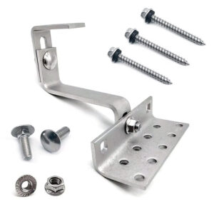
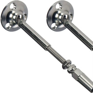
Customer-supplied anchoring hardware introduces a separate risk layer. When screw and bolt configurations are determined by the installer or customer based on floor surface rather than specified on the drawing, the hardware at each post position may differ in holding behavior even when it appears dimensionally equivalent. That variation doesn’t always produce visible movement immediately — it may only become apparent when lateral load is applied, or when temperature cycling causes minor positional drift that the spigot adjustment range can no longer accommodate.
| Facteur | What Determines Stability | Risk If Not Addressed |
|---|---|---|
| Substrate condition at post locations | Wood, concrete, or steel substrate – verification of required blocking | Base plate may shift, multiplying alignment errors across the run |
| Customer-supplied base connecting hardware | Screws, bolts, anchor bolts – depend on floor surface | Hardware mismatch introduces shift, increasing adjustment burden and rework potential |
The downstream consequence of base-plate shift isn’t limited to that post. Each shift changes the effective gap dimension for the adjacent panel, which changes the edge distance at the next spigot, which — if the panel is already drilled — forces a choice between accepting a gap that is out of tolerance, shimming in a way that the hardware doesn’t cleanly support, or replacing the panel. Verifying substrate condition and specifying anchoring hardware on the drawing is the point of intervention that prevents that cascade, not hardware adjustment on site.
Drawing freeze checks before glass drilling
Releasing shop drawings before the installation conditions are fully resolved transfers the design decision burden to the installer, who must then interpret ambiguous drawings under site pressure. The result is predictable: posts get set based on assumptions that conflict with the actual guard condition, glass thickness, or cap rail geometry, and the conflict surfaces only after drilling.
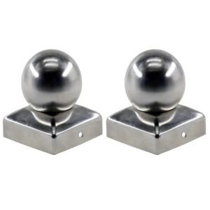
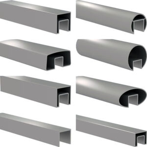
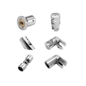
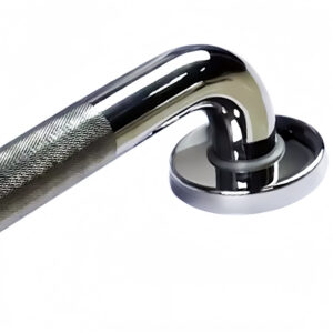
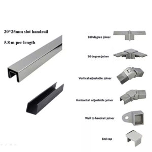
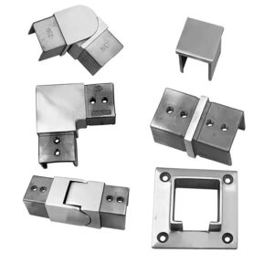
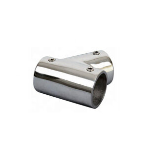
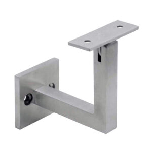
Pour post to glass adapters and spigot hardware, the drawing must fix four things before fabrication proceeds: the guard location and required height at each condition (stair, balcony, overlook), the glass specification including thickness, type, and any tint or finish, the panel layout with approximate widths and corner or termination details, and the handrail plan including cap rail profile or wall-mounted route and returns. Each item affects spigot position or post height in a way that cannot be corrected after glass is drilled.
| Item to Confirm | Why It Matters for Spigot Alignment | Risk If Left Unresolved |
|---|---|---|
| Guard locations (stairs, balcony, overlook) and required heights | Different guard conditions directly affect spigot placement | On‑site rework or improper alignment may be needed |
| Glass thickness/type (tempered or laminated) and tint/frosted finish | Glass weight and strength influence spigot design and panel fit | Dimensional mismatches can occur after drilling |
| Panel layout targets (approximate widths) and corner/termination details | Spigot positions must align with panel widths and corner gaps | Alignment feasibility is reduced, increasing on‑site adjustment |
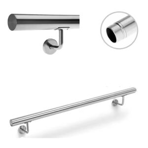
| Handrail plan (cap rail profile or wall-mounted route and returns) | Cap rail requirements alter post height and spigot alignment | Post‑fabrication conflicts can arise if handrail plan is not frozen |
The logic of drawing freeze is not procedural formality — it is about which party absorbs the cost of unresolved decisions. Fabrication that proceeds on incomplete drawings shifts rework cost to the installer and the glass supplier. Freeze checks performed before release keep that cost at the drawing stage, where it is resolvable without material consequence. For custom drilled glass specifically, the cost of releasing early is measured in replacement panels, not revisions.
For a detailed walkthrough of how these planning steps map to physical installation sequence, the post-mounted glass railing system installation guide covers spigot placement and adjustment in step-by-step form.
The most consequential decision in post-mounted glass railing work is not which spigot hardware to select — it is whether the layout has been resolved to the point where fabrication can proceed without creating misalignment that site conditions will expose. That means confirming centerlines and edge distances against panel width and spacing thresholds, understanding how substrate conditions affect base-plate stability across a full run, and holding the drawing until all four freeze-check items are documented and consistent with each other.
Before releasing glass for drilling, confirm that field measurements have been taken to the tolerance your panel fit requires, that substrate conditions at each post location have been verified and specified, and that the anchoring hardware is defined on the drawing rather than left to site determination. Those confirmations are where alignment risk is controlled — not during leveling, and not through hardware adjustment after panels arrive.
Questions fréquemment posées
Q: What happens if site conditions prevent field measurements from reaching the 1/4-inch tolerance threshold before glass is ordered?
A: Do not release the glass for drilling until conditions allow measurements to meet that threshold. The 1/4-inch figure is an operational gate, not a guideline to round against — if the substrate is unstable, posts aren’t fully set, or measurement access is limited, releasing glass on looser measurements transfers the cost of that uncertainty into panel replacement rather than schedule delay. Stabilize the substrate, set and verify each post position, and re-measure before committing the order.
Q: Does adding more spigots along a run improve alignment reliability, or does it introduce more risk?
A: It does both, and the balance depends on run length and layout precision. More spigots distribute load more evenly and can help satisfy spacing limits, but each additional spigot is another point that must land within field tolerance — and each additional visible hardware position increases layout labor. On longer runs where cumulative base-plate deviation is already a concern, adding spigots without tightening the layout process multiplies the number of positions that can stack error, not reduce it. The decision should follow from the panel width and spacing thresholds already established in the drawing, not from a general assumption that more support is safer.
Q: Is this planning approach equally necessary for short runs of only two or three panels, or does it mainly apply to long installations?
A: The drawing freeze checks and centerline verification matter on any run where glass is custom drilled, regardless of panel count. A two-panel run with a corner termination still requires the edge distance calculation at that termination — leaving it to visual judgment on site produces the same inconsistency at the most visible part of the run. What changes with run length is the cumulative tolerance risk: base-plate shift compounds across many posts in a way it cannot across two or three. But the upstream planning steps — confirmed centerlines, frozen glass spec, verified substrate — apply regardless of how many panels are in the run.
Q: How should the anchoring hardware be specified on the drawing when the floor substrate varies along the same run — for example, concrete at one end and wood framing at another?
A: Each post location should be specified individually against its confirmed substrate condition, not assigned a single hardware type for the full run. Concrete and wood framing require different anchoring methods and may require different blocking details, and a single specification across mixed conditions creates the exact mismatch risk the article identifies — hardware that appears dimensionally equivalent but behaves differently under load or thermal cycling. The substrate type, blocking requirement, and fastener specification should all be documented per post position before drawings are released.
Q: At what point in a project should a structural engineer or code consultant review the spigot layout against IBC load requirements, rather than relying on internal drawing review?
A: Before drawings are frozen and certainly before glass is drilled. The 6-foot post spacing maximum under IBC guardrail load is a threshold that applies to the full layout, not just individual post positions, and projects with unusual conditions — stairs, elevated overlooks, commercial occupancy loads, or jurisdictions with local amendments — may require formal engineering review to confirm that the layout as drawn satisfies the applicable standard. Internal drawing freeze checks are a quality control step for fabrication readiness; they are not a substitute for engineering judgment on whether the post-mounted system meets the structural requirements of ASTM E985 or the governing code for the specific project condition.