A cable railing record showing terminal pull-test numbers or wire rope breaking strength tells a buyer something true about that component. It does not tell a project team whether the installed guard assembly meets the applicable code. That gap between a component fact and a system conclusion is where specification decisions go wrong, and it is the question every cable tensioner selection eventually has to answer.
Component Records and Their Evidence Limits
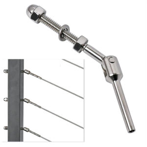
A cable tensioner, terminal, or threaded fitting typically arrives with some form of manufacturer documentation: a load rating, a material specification, a compatible wire diameter. This documentation describes the part as tested or rated within the manufacturer’s own scope. It does not describe what happens when that part is installed into a specific post spacing, anchored to a specific base condition, and tensioned to a specific load within a guard assembly.
The distinction matters because a component record and a system record answer different questions. A component record answers: does this tensioner, this terminal, this length of cable perform as specified when tested under the conditions the manufacturer used? A system record answers: does the installed guard, built from these parts in this configuration, meet the structural and code performance expected of a guard assembly? The first does not establish the second. A cable or threaded-part record can describe that component within its source scope, but it does not establish the performance of the installed guard assembly.
Where a buyer treats a strong component rating as proof of system performance, the assumption fails at the point where configuration enters the picture. Post spacing changes the span the cable must resist. Corner conditions change how tension transfers through the run. Anchor and base conditions change whether the structure behind the railing can carry the load the cable delivers to it. None of these are properties of the tensioner itself; they are properties of the assembly the tensioner is installed into.
This matters most at the procurement stage, when a cut sheet or component data sheet is the only document in hand. A data sheet showing a tensioner’s rated capacity is useful for confirming that the part is suitable for the cable diameter and tension range intended. It is not evidence that the finished railing, once built, will satisfy a guard load requirement or an opening-size requirement written into a building code. Where a procurement team or project buyer needs to document code compliance, the component data sheet is necessary information but an incomplete answer, and asking for it alone leaves the system question unresolved.
Installed Configuration Needed for System Claims
If a project needs evidence that the installed guard assembly performs as required, the evidence has to describe the assembly, not just a part within it. System evidence should identify the tested or calculated configuration, including cable, terminals, posts, bases, anchors, spacing, corners, tensioning condition, and applicable load path. Each of these elements changes what the evidence can support once it is confirmed or altered.
The cable and terminal pairing establishes how load transfers from the infill into the end connection. The post and base pairing establishes how that load transfers into the structure. Anchor type and condition determine whether the base connection can deliver that load into the floor, wall, or framing member it attaches to. Spacing between posts determines the span the cable sees and therefore the deflection and tension behavior under applied load. Corner conditions change how tension is maintained or redirected around a turn, which affects whether the same tensioning approach used on a straight run remains valid. Tensioning condition — how the cable is pre-tensioned and what method is used to achieve and maintain that tension — determines whether the system behaves as modeled or calculated, or diverges from it.
Where any one of these elements is missing from the documentation a buyer is given, the evidence describes only part of the assembly, and the remaining elements become open questions rather than confirmed conditions. A buyer reviewing a submittal or test report for a cable railing project should look for all of these elements named together, in the configuration actually proposed for the project, rather than accepting a report that names only the cable and tensioner.
This is also the point where project information supplied to a hardware supplier becomes useful rather than incidental. When a buyer provides post spacing, anchor type, corner locations, and intended tensioning method as part of a quotation or configuration request, that information allows the supplier’s component recommendation to be matched to the assembly actually being built, rather than offered as a generic part selection. The supplier’s configuration response is only as specific as the project information it receives.
Jurisdiction and Adopted-Code Identification
Before any compliance question about a نظام درابزين الكابلات can be answered, the applicable code has to be identified, because the guard criteria that apply depend on which code governs the project and which occupancy or use the project falls under. Start with the jurisdiction and adopted code because residential, commercial, workplace, and international projects can apply different guard criteria.
This step precedes any discussion of spacing, load, or tensioning requirements, because those requirements are defined within a code, and different adopted codes can define them differently. A project governed by a residential code may apply different guard and opening criteria than one governed by a commercial building code, and a workplace safety standard may impose separate requirements again. The 2021 International Building Code, for example, establishes scope and requirements for means of egress, including handrails and guards, but its applicability depends on whether it is the code actually adopted — in its published form or as locally amended — by the jurisdiction where the project sits. A code citation that is accurate in general terms is not useful if the jurisdiction has adopted a different edition or a modified version of it.
This is also why a compliance conclusion cannot be drawn from a standard’s title or general scope alone. ASTM E985 addresses basic design and load/deflection criteria for permanent metal railing systems, but field conditions and project-specific criteria remain the responsibility of the designer, specification writer, and code authority, not the standard itself. A standard establishes criteria; it does not confirm that a specific installed configuration in a specific jurisdiction satisfies those criteria.
The practical consequence for a buyer or project team is that code identification is a prerequisite step, not a parallel one. Attempting to evaluate spacing, load capacity, or tensioning evidence before confirming which code and which edition applies to the project risks evaluating the assembly against the wrong criteria entirely, even when every other piece of documentation is accurate.
Posts Anchors Openings and Tensioning in the Load Path
Each element in a cable guard assembly sits somewhere in the load path, and understanding what each one does clarifies why a change to one element changes what the rest of the system needs to do. The load path begins at the point someone or something contacts the guard, continues through the cable infill, transfers at the terminal into the post, and ends at the anchor connecting the post to the structure.
Posts carry the horizontal load applied to the cable infill into bending or shear at the base. Where post spacing increases, the span each cable segment covers increases, which changes the tension and deflection behavior of that segment under the same applied load. Anchors carry the load delivered by the post into the surrounding structure, and the anchor’s suitability depends on what that structure is — a concrete slab, a wood-framed deck, a steel ledger — because each substrate accepts load differently. Openings, meaning the gaps between cables or between a cable and an adjacent surface, are governed by the guard’s intended function of restricting passage, and the opening dimension depends on both cable spacing and how much a cable can deflect under load, since a cable that deflects significantly under applied force can change the effective opening size during use.
Tensioning is the condition that ties these elements together. A cable guard depends on maintained tension to behave predictably; if tension is lost or set incorrectly, the cable’s deflection under load changes, which changes both the opening dimension and the way load transfers to terminals and posts. This is why tensioner selection is not a question of hardware alone — it is a question of how the tensioning method chosen interacts with the spacing, anchor condition, and corner geometry already fixed by the design.
Where a buyer is sourcing tensioners, terminals, and related cable hardware for a project, reviewing how those components fit the assembly’s spacing, anchor, and corner conditions is part of confirming the component is appropriate for its position in the load path, not a separate afterthought to placing the order.
Tested or Calculated Configuration Boundaries
| Evidence situation | Supported interpretation | Project decision boundary |
|---|---|---|
| A cable or threaded-part record describes the item within its stated source scope | The record supports the identified component only | Do not use it to establish performance of the installed guard assembly |
| System evidence identifies the tested or calculated cable, terminals, posts, bases, anchors, spacing, corners, tensioning condition, and applicable load path | The evidence can be assessed against the identified installed configuration within the source scope | Identify the jurisdiction and adopted project code before making a project-specific code conclusion |
| The installed assembly differs from the tested or calculated configuration | The supplied evidence does not automatically extend to the changed configuration | Treat the deviation as a design question for the project professional and approval authority |
| The jurisdiction or adopted code has not been identified | Residential, commercial, workplace, and international projects can apply different guard criteria | Verify the locally adopted code before relying on a clause or making a compliance conclusion |
Once a buyer has configuration information and a candidate piece of evidence — a test report, a calculation package, a component data sheet — the next judgment is whether that evidence applies to the specific assembly being built. This is a boundary question, and it depends on comparing what was tested or calculated against what is actually installed.
Evidence that describes a cable or threaded part within its stated source scope supports conclusions about that component alone. Evidence that identifies the tested or calculated cable, terminals, posts, bases, anchors, spacing, corners, tensioning condition, and load path together can be assessed against an installed configuration that matches those same elements, but only within the scope the source document states — and only once the applicable jurisdiction and adopted code have been identified, since the same tested configuration can be read against different criteria depending on which code governs.
Where the installed assembly differs from the tested or calculated configuration in any of these elements — a wider post spacing, a different anchor type, an added corner, a different tensioning method — the supplied evidence does not automatically extend to cover the changed configuration. The deviation does not necessarily mean the assembly fails; it means the existing evidence no longer speaks to it, and a new determination is needed.
This is the recurring judgment a buyer or project team has to make when evaluating submittals: is the proposed installation the same configuration the evidence was generated for, or a variation of it? A variation in spacing changes the span and therefore the tension behavior. A variation in anchor type changes whether the tested load transfer into structure still applies. A variation in corner count changes how tension is distributed around the run. Each of these is a reason to ask the manufacturer or engineer who generated the evidence whether it still applies, rather than assuming similarity in appearance or component sourcing is sufficient.
Approval Questions After Any Assembly Change
When a cable railing assembly departs from its tested or calculated configuration, the question of what to do next belongs to the project professional and the approval authority, not to an assumption that the original component evidence still covers the new condition. Treat deviations from the evidenced configuration as design questions for the project professional and approval authority rather than as automatic extensions of a component report.
This reframes how a buyer should treat a change discovered midway through a project — a post relocated to avoid an obstruction, a corner added where none was in the original layout, a different anchor substrate encountered on site. None of these are hardware questions alone. Each one changes an element of the load path, and the right next step is to route the change to whoever is responsible for confirming that the assembly still satisfies the applicable code — the architect or engineer of record, and ultimately the authority that approves the installation.
Where the change is minor relative to the tested configuration, the project professional may be able to confirm continued suitability relatively directly. Where the change alters spacing, anchor type, or tensioning method in ways that move further from the tested condition, a new calculation or a new test may be the only way to re-establish evidence for the changed assembly. Which of these applies is not something a component supplier or installer can determine without the project professional’s involvement, since it depends on engineering judgment about how the change affects the load path.
For the buyer, the practical implication is that assembly changes discovered during fabrication or installation should be documented and routed for approval before the installation proceeds on the assumption that the original evidence still applies. A supplier’s cable hardware and fittings can be reconfigured to match a revised layout, but confirming that the revised layout still satisfies the project’s adopted code is a determination that sits with the project professional and the approval authority, not with the hardware configuration itself.
الأسئلة الشائعة
س: Can a cable or tensioner report prove that the complete railing meets the project code?
A: No. A cable or threaded-part record supports only that component within its stated scope. Evidence for the complete guard must address the identified installed configuration, including the terminals, posts, bases, anchors, spacing, corners, tensioning condition, and load path.
س: What project information should be prepared before reviewing cable-railing evidence?
A: Start with the project jurisdiction, locally adopted code, and whether the installation is residential, commercial, workplace, or international. Then document the proposed cable, terminals, posts, bases, anchors, spacing, corners, and tensioning condition so they can be compared with the tested or calculated configuration.
س: Can existing system evidence still be used after the post spacing, anchors, corners, or tensioning arrangement changes?
A: It does not automatically extend to the changed assembly. Identify each deviation from the evidenced configuration and treat it as a project-specific design question for the project professional and approval authority.
س: How should ASTM, IBC, and ISO documents be used together for a cable-railing review?
A: Use each document only within its stated scope. ASTM E985 addresses permanent metal railing systems, the IBC provides guard and means-of-egress criteria subject to local adoption, and ISO 2408 addresses steel wire rope requirements; none of these references alone establishes that a particular installed cable-railing assembly complies with the project code.