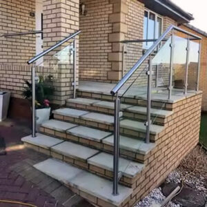
Anchorage details that look complete on paper have a reliable way of surfacing problems at the worst possible moment — after fabrication is locked and posts are on site. A base plate sized for a 4-inch embedded pocket installed against an 8-inch concrete curb, or a wall bracket specified without confirmed backing and anchor access, creates field conditions that force either rework or a compromised installation that may not hold up under inspection. The friction is rarely in the hardware itself; it sits in the gap between who owns the anchor design and whether substrate conditions, edge clearances, and load assignments were actually confirmed before the anchor package was released. Understanding where each anchorage type carries load, which substrate conditions change the design method, and what documentation the engineer of record needs to accept the package is what separates a buildable anchorage scope from one that stalls at the submittal stage.
Anchorage scope across base plates, wall brackets, and fasteners
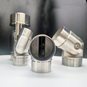
Three anchorage configurations cover most stainless steel railing installations, and the critical planning error is treating them as interchangeable. Embedment in a grouted pocket and surface-mounted base plate with post-installed anchors both provide primary vertical and lateral support, but they impose different sequencing demands, substrate requirements, and engineering inputs. Wall brackets occupy a different category entirely: they deliver lateral support locally, typically at railing terminations, and are not a substitute for floor anchorage under any loading condition.
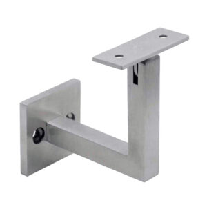
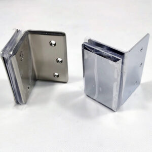
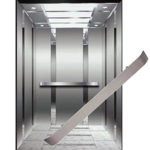
The distinction matters because wall brackets are often specified for visual reasons — they sit closer to the structure and leave no base plate visible at floor level — without a parallel confirmation that backing exists at the anchor locations or that the bracket geometry accommodates the minimum 1½-inch handrail clearance from the wall surface. That clearance figure is not incidental; it directly affects whether a fastener can be installed and tightened once the bracket is in position. Specifying brackets in locations where backing is unconfirmed or clearance is marginal creates an installation conflict that only becomes visible on site, after the post schedule is set.
For embedded and surface-mounted configurations, the engineering principles differ. A grouted pocket relies on the bond and bearing of the grout column; grout material selection and hole geometry are load-carrying decisions, not field substitutions. A surface-mounted base plate transfers moment through a tension-compression couple between the post-installed anchors in tension and the bearing contact zone of the plate — which means anchor type, edge distance, plate size, and substrate capacity all participate in the same load path simultaneously. Dissimilar metals in contact at the anchor zone also introduce electrolytic corrosion risk; isolating stainless steel base plates from carbon steel structure or concrete reinforcement with bushings, grommets, or washers is a durability requirement, not an optional detail.
Each configuration’s scope, support role, and governing design factors can be read side by side here.
| Anchorage Type | Primary Support | Key Design Considerations | Typical Limitations |
|---|---|---|---|
| Embedment in grout (core-drilled pocket) | Vertical and lateral | Grout material selection; hole diameter/depth; coordination with reinforcing steel | Requires core drilling; often unfeasible in thin or narrow substrates |
| Surface-mounted base plate with post-installed anchors | Vertical and lateral (via moment couple) | Anchor type; edge distance; tension/compression couple; base plate size; isolation of dissimilar metals to prevent electrolytic corrosion | Visible base plate; depends on substrate capacity; demands precise anchor installation |
| دعامة حائط | Lateral only, primarily at terminations | Bracket geometry; anchor access; minimum 1½ in. handrail clearance from wall | Cannot carry primary vertical load; dependent on backing and anchor strength; limited by handrail clearance |
The takeaway for specifiers and project teams is not that one configuration is preferable, but that each has a defined scope of load transfer. Assigning wall brackets a role they cannot perform, or releasing embedded anchorage details without confirming grout selection and hole feasibility, turns a documentation gap into a field problem.
Concrete and steel structure differences in anchor selection
Substrate type is not a background variable in anchor selection — it determines which design method, which code pathway, and which anchor products are applicable. Concrete and steel structures impose different design approaches, and treating them interchangeably produces anchor selections that cannot be verified through calculation or accepted in a submittal.
For anchorage to concrete, the 2018 IBC routes the design through ACI 318 Chapter 17, which governs post-installed and cast-in anchor capacity, failure modes, edge distance, and concrete condition assumptions. This is a distinct analytical framework from the approaches used for anchorage to steel framing, and it requires specific inputs: concrete compressive strength, whether the concrete is assumed cracked or uncracked, minimum edge and corner distances, and the geometry of the concrete member itself. These inputs are not interchangeable between projects — a thin balcony slab and a cast-in-place grade beam present fundamentally different anchor capacity environments even if the surface hardware looks identical.
Steel substrates introduce a different set of considerations. Anchor bolts connecting to steel framing follow different capacity checks, and the connection detail depends on the framing member’s thickness, orientation, and whether through-bolting or weld-on inserts are feasible. Where stainless steel hardware connects to carbon steel structure, the same dissimilar-metal isolation requirement applies: direct contact between the two materials under moisture exposure is a corrosion risk that shortens service life and can compromise the connection at the substrate interface over time.
The practical implication is that the anchor selection conversation cannot start at the hardware catalog. It starts at the substrate: what material, what geometry, what condition, and which design method governs. Specifying anchors before those inputs are confirmed produces a selection that may be technically credible on its own but cannot be validated against the actual installation condition. GB/T 1231-2024 addresses high-strength bolt assembly requirements for steel structures and provides a relevant reference point for bolt-grade and assembly performance in steel substrate applications, though the applicable design standard for any given project jurisdiction should be confirmed separately.
Epoxy versus wedge anchors under site and approval constraints
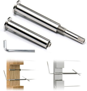
Anchor type selection between epoxy and wedge systems is ultimately a project-specific judgment, driven by site conditions and approval constraints rather than a universal preference for one over the other. Neither type is inherently superior; each performs well within its applicable range and fails predictably outside it.
Wedge anchors rely on mechanical interlock with the concrete and are generally faster to install — no mixing, no cure wait, immediate torque-to-load. That speed is an advantage in dry, uncracked concrete with adequate edge distance and no sustained tensile load concerns. The constraint is that wedge anchors are sensitive to edge distance violations, cracked concrete conditions, and cyclic loading; where any of those conditions apply, the mechanical expansion mechanism may not develop the capacity assumed in the design.
Epoxy anchors introduce a curing window that affects installation sequencing but offer broader applicability in cracked concrete, close-edge conditions with supplemental reinforcement, and applications requiring higher pull-out resistance in lower-strength concrete. The constraint is that performance depends on hole cleanliness, mixing ratio, ambient temperature during cure, and whether the anchor is installed in a dry or saturated hole — all of which are field execution variables, not factory-controlled conditions. Epoxy systems also typically require documented approval from the anchor manufacturer for specific concrete conditions, and that approval documentation becomes part of the submittal package.
The approval constraint is where projects often stall. If an epoxy anchor is specified but the manufacturer’s approval data for the specific concrete condition — cracked, uncracked, minimum edge distance, compressive strength — is not in the submittal, the engineer of record cannot accept it. Switching anchor types after the submittal has been returned is a schedule event, not just a procurement swap. The practical check is to confirm anchor type, concrete condition assumptions, and required approval documentation simultaneously, before the anchor package is issued for submittal. For outdoor or exposed marine conditions, the anchor material grade — typically 316 stainless for salt-air environments — should also be confirmed at the same stage, not after corrosion is observed in service.
Fastener documentation needed for structural submittals
Incomplete fastener documentation is one of the most consistent reasons structural submittals are returned without approval. The problem is not usually missing hardware information — product data sheets are readily available — but missing calculations, unsealed drawings, or load-path documentation that the engineer of record needs to verify that the anchor actually works in the specific installation condition.
The delegated designer’s role in this workflow is to produce calculations and sealed shop drawings that demonstrate load paths, structural capacity, and anchor coordination with embedded items. These are reviewed by the engineer of record, not simply filed. That review step is where gaps in anchor edge distance, substrate assumptions, or missing manufacturer approval data become rejection points. Submitting hardware specifications without the supporting engineering documentation reduces the package to a catalog submission, which the engineer of record has no basis to approve for a structural connection.
The full scope of what a submittal package must carry goes beyond calculations alone.
| Submittal Component | What It Must Include / Address |
|---|---|
| Calculations and sealed shop drawings | Load paths, structural capacity, anchor coordination with embedded items; must be reviewed by the engineer of record |
| Product data | Specifications, performance data for anchors and components |
| Shop drawings | Plans, elevations, details, materials, finishes, fittings, fasteners, anchorages |
| Setting diagrams and templates | Anchor locations, embedment depths, drilling layout |
| Installation instructions | Step‑by‑step procedures, torque values, curing times |
| Manufacturer’s certificates | Compliance with referenced standards, product qualifications |
Each line in that checklist is a potential rejection point if missing. Setting diagrams and templates are often omitted because they feel like field coordination documents rather than submittal content, but they establish anchor locations, drilling layout, and embedment depths in a format the engineer of record can check against the structural drawings. Installation instructions and torque values matter because over- or under-torqued anchors can reduce capacity without visible indication, and the manufacturer’s stated values are part of the basis for the anchor’s performance documentation.
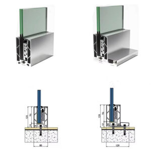
For projects using ألواح قاعدة مثبتة على السطح أو fascia mount base plates, confirming that the base plate dimensions and anchor pattern are reflected in the shop drawings — not just in the product data — is a practical review check before the package is submitted. Discrepancies between the plate geometry shown in the drawing and what is on the product sheet are a common source of revision requests.
Anchor package readiness after substrate, load, and report needs are confirmed
Releasing the anchor package before substrate, load, and report conditions are simultaneously confirmed is one of the more expensive mistakes in a railing project schedule. The fabrication clock starts when the package is released; if a field conflict surfaces after posts are cut, drilled, or delivered, the correction cost is carried by whoever owns the error — and that question of ownership is often unresolved until the problem is already on site.
Readiness is not a sequential process where each condition is confirmed and checked off in order. Edge distance is connected to rebar placement, which is connected to slab geometry, which is connected to the assumed concrete condition, which feeds the anchor capacity calculation. If any one of those variables changes late — a post relocated two inches to avoid a rebar conflict, a curb identified as too narrow to accommodate the embedded pocket — the anchor selection that was documented in the submittal may no longer be valid. The 8-inch curb condition is a useful reference point here: a 4-inch embedded pocket in that substrate leaves insufficient edge distance on either side, and that condition cannot be resolved by specifying a higher-strength anchor. The geometry is simply unbuildable as designed, and it must be caught before fabrication, not during installation.
Load confirmation deserves the same parallel treatment. The applicable IBC loading figures — 200-pound concentrated load or 50 pounds per lineal foot applied in any direction for handrails, with 50 plf horizontal plus 100 plf vertical for guard top rails and 200 pounds concentrated for infill — are the load inputs that the anchor design must satisfy. Post spacing affects which load case governs: when spacing exceeds 4 feet, the 50 plf distributed load typically controls. These are design figures drawn from applicable code inputs; the specific values governing any project depend on the applicable edition and jurisdiction, which is a confirmation step, not an assumption.
The tolerance review is where readiness checks most often stop short. A 6-inch edge distance with preferred edge bar placement may leave only approximately ¾ inch of clearance before the anchor conflicts with the bar or falls below breakout capacity thresholds. That margin does not accommodate railing setting tolerances, rebar placement tolerances, and concrete form deviation simultaneously. Each of those tolerance sources is real, independent, and additive — treating the design edge distance as a reliable field condition without accounting for construction tolerances in the anchor package is a common source of inspection failures.
The full set of confirmation areas, thresholds, and associated risks before package release can be reviewed here.
| Confirmation Area | Key Condition / Threshold | Risk if Unconfirmed |
|---|---|---|
| Design loads | Handrail: 50 plf uniform, 200 lb concentrated; guard top rail: 50 plf horizontal + 100 plf vertical; infill: 200 lb concentrated; when post spacing >4 ft, 50 plf governs | Anchorage may be under‑designed for code loads |
| Concrete substrate parameters | Minimum edge/corner distances; cracked vs. uncracked concrete assumption; concrete compressive strength specified in contract documents | Anchor capacity miscalculation; sudden breakout failure |
| Constructability and edge clearances | 8‑in wide curb cannot accommodate a 4‑in embedded hole or sufficient anchor edge distance; 6‑in edge distance with preferred edge bar leaves only ¾ in clearance | Unbuildable anchorage detail; forced rework or capacity reduction |
| Reinforcing steel coordination | Avoid interference with reinforcing steel; presence of confining steel greatly affects allowable edge distance; thin balconies require slab‑thickness and rebar coordination | Loss of edge capacity; post installation conflicts |
| Construction tolerances | Railing setting tolerances, rebar placement tolerances, cover requirements, post edge distances, deviation of formed surfaces | Misalignment, inadequate edge clearance, refusal during inspection |
| Corrosion protection | Isolate dissimilar materials with bushings, grommets, or washers | Electrolytic corrosion, long‑term durability failure |
Preinstallation meetings that include the contractor, architect, fabricator, installer, and relevant subcontractors are a practical process step for aligning these conditions before the anchor package is issued. The meeting forces confirmation that each anchor condition has been assigned to a substrate, reviewed for site feasibility, and connected to the load and documentation requirements it must satisfy. Without that alignment, responsibility for anchor design tends to fall into the gap between parties — each assuming another owns it — which surfaces only when submittals return without approval or an inspector identifies a condition that cannot be corrected without rework. ASTM E894-88(2004) addresses anchorage of permanent metal railing systems and provides a relevant reference framework for understanding the performance expectations that anchor design is intended to meet in that context. For further guidance on anchor bolt sizing and torque requirements specific to concrete substrates, the concrete post mounting article on this site addresses that scope in more detail.
The practical risk in stainless steel handrail anchorage is not selecting the wrong anchor from a catalog — it is releasing an anchor package before the conditions that govern its performance have been confirmed and connected to each other. Substrate type, concrete parameters, edge clearance, rebar placement, post spacing, and load case are not independent checklist items; they are variables in the same capacity calculation, and late changes to any one of them can invalidate an anchor selection that passed a desk review.
Before fabrication is released, confirm that each anchor condition is assigned to a specific substrate, that edge distances have been checked against construction tolerances and rebar placement, that the load inputs match the applicable code figures for the project jurisdiction, and that the submittal package includes sealed calculations, shop drawings, and manufacturer approval documentation in a form the engineer of record can act on. That confirmation step is what separates an anchor detail that holds under load and inspection from one that creates a rework event after the post schedule is locked.
الأسئلة الشائعة
Q: Who is responsible for the anchor design when the railing supplier, installer, and structural engineer are all involved in the same project?
A: Responsibility must be explicitly assigned in the contract documents before fabrication begins — it does not default to any one party automatically. In practice, the delegated designer produces sealed calculations and shop drawings that the engineer of record reviews for load path, capacity, and coordination with embedded items. The friction point is that railing suppliers typically provide hardware geometry and load inputs, while installers execute the field work, leaving the actual anchor design in a gap unless a delegated designer is named and scoped early. Leaving this unresolved means responsibility only surfaces when a submittal is returned or an inspector identifies a field condition that cannot be corrected without rework.
Q: What happens to the anchor selection if the concrete member dimensions or rebar placement change after the package has been submitted?
A: The anchor selection may no longer be valid and must be re-evaluated before installation proceeds. Edge distance, rebar placement, concrete geometry, and anchor capacity are variables in the same calculation — a two-inch post relocation to avoid a rebar conflict, or a curb identified as narrower than assumed, can push the design below breakout capacity thresholds or make the configuration geometrically unbuildable. Because construction tolerances from railing setting, rebar placement, and formed surfaces are independent and additive, the design edge distance in the submittal should never be treated as a reliable field condition without a tolerance review. Any late change to substrate geometry should trigger a re-check of the anchor capacity calculation before installation continues.
Q: Is surface-mounted base plate anchorage a reliable alternative to embedment on thin concrete balconies, or does the substrate condition make it unsuitable?
A: Neither configuration is automatically suitable for thin balconies — the substrate condition determines which, if either, is buildable. Embedded pockets require sufficient slab thickness to develop the grout column without compromising cover, and they must be coordinated with reinforcement steel location to avoid capacity loss. Surface-mounted base plates require adequate edge distance and concrete compressive strength to develop the tension-compression couple in the load path, which is also sensitive to slab thickness and rebar proximity. On thin balconies, both approaches demand early coordination of post anchorage with slab geometry and reinforcement layout; selecting one over the other without that coordination produces an anchor condition that looks valid on paper but fails the capacity check once actual substrate parameters are entered.
Q: Can wall bracket hardware from a railing supplier be submitted as the primary anchorage documentation, or does it require additional engineering input?
A: Wall bracket product data alone is not sufficient for a structural submittal where the brackets are providing primary lateral support at railing terminations. The submittal package must include sealed calculations demonstrating load path and capacity, shop drawings showing anchor locations and embedment depths, and confirmation that backing exists at each bracket location. For non-pipe railing systems specifically, manufacturer details may require engineering input beyond standard pipe railing guidance. Submitting only product data shifts the burden to the engineer of record to verify conditions that should already be resolved — and that typically results in a return without approval. Bracket geometry, anchor type, backing material, and the 1½-inch minimum handrail clearance from the wall surface all need to be documented in a form the engineer of record can act on.
Q: At what point in the project schedule is it too late to change anchor type from wedge to epoxy, or vice versa, without causing a significant delay?
A: Changing anchor type after a submittal has been returned without approval is effectively a schedule event, not a procurement swap. Epoxy systems require manufacturer approval documentation for the specific concrete condition — cracked or uncracked, minimum edge distance, compressive strength — and that documentation must be part of the submittal before the engineer of record can accept it. If the anchor type changes, a revised package with updated calculations, approval data, and potentially revised shop drawings must be resubmitted and re-reviewed. The practical cutoff is before the anchor package is issued for submittal: anchor type, concrete condition assumptions, and required approval documentation should be confirmed simultaneously at that stage. For exposed or marine environments, anchor material grade — typically 316 stainless for salt-air conditions — should also be locked at the same point, not after installation.