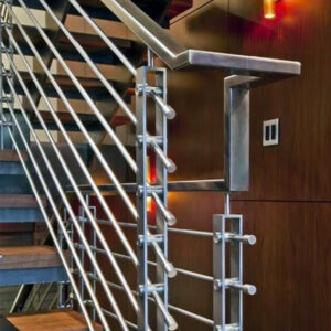
A guardrail that measures 3.75 inches between cables at installation can still fail inspection if the cables deflect enough under a 50-pound push to open a gap a 4-inch sphere can pass through. That failure means re-tensioning, adding cable rows, or relocating posts after the system is already anchored—rework that costs significantly more than the hardware adjustment would have during layout. The decision that prevents it is not choosing a nominal spacing figure; it is working backward from the deflection behavior of the installed system to set spacing, tension, and post stiffness together. What follows gives contractors and project teams the criteria to make that judgment before the field check, not after.
Installed Openings Versus Nominal Cable Spacing
Nominal spacing is a design input, not a compliance result. What the inspector evaluates is the opening that exists when cables are deflected—pushed by hand or tested with a 4-inch sphere—not the dimension stamped on a shop drawing. This distinction matters because the two values can diverge meaningfully depending on post stiffness, cable tension, and run length, and no static measurement taken before loading will reveal the gap.
The 4-inch sphere rule and the 50-pound concentrated load requirement define the performance thresholds the installed system must satisfy. Neither specifies a nominal cable spacing. That means the designer or installer must work backward: if a loaded cable can deflect by a meaningful fraction of an inch at mid-span, the nominal spacing needs to be set correspondingly tighter to keep the installed opening below the sphere threshold under load.
| متطلبات الكود | What the Inspector Checks | Effect on Cable Spacing Design |
|---|---|---|
| 4‑in. sphere rule | Can a 4‑in. sphere pass through any opening when cables are deflected? (Inspectors may push or use a sphere.) | Nominal cable spacing must be set smaller than 4 in. to keep the installed opening below 4 in. under loading. |
| 50‑lb concentrated load | Cable infill must resist a 50‑lb force applied over a 1‑sq‑ft area without failing or creating non‑compliant openings. | Post spacing, cable tension, and end‑post stiffness must be designed together to limit deflection so that openings remain under the allowable maximum. |
The 50-pound load criterion compounds the sphere rule rather than replacing it. A system that holds its geometry under a static push but allows a cable to yield visibly when a distributed load is applied has not met both thresholds. Post spacing, cable tension, and end-post anchorage all affect the outcome under that load, which is why none of those variables can be decided in isolation from the others.
Deflection Contributions From Posts and Terminals
Cable deflection does not come only from cable elasticity. Posts that flex, end posts that rotate under cumulative tension, and terminals that allow even small amounts of cable draw all contribute to the installed opening size. A system designed around cable properties alone—without accounting for post stiffness and anchor behavior—will often underestimate total deflection at the point where the sphere test is applied.
Intermediate post spacing is one of the most direct controls available. General industry guidance recommends keeping intermediate posts no more than 4 feet on center; at greater spans, mid-run deflection under the 50-pound load test can open gaps that would not appear in a static inspection. Cable tension works alongside post spacing: for 1/8-inch cable, a planning range of approximately 70 to 200 pounds per cable reflects the balance between enough tension to limit sag and enough restraint to avoid distorting the top rail. Over-tensioning is not a safety-side error—it can bow the top rail and redistribute load in ways that actually reduce the system’s stiffness under lateral pressure.
End and corner posts carry the cumulative force from every tensioned cable in the run. An illustrative example with 10 to 13 cables produces roughly 1,300 pounds of horizontal force on the end post. That figure is not a code limit; it is a planning signal that end posts require substantially stiffer sections and more robust base anchoring than intermediate posts, and that the anchor pullout capacity needs to be verified against the actual cable count and tension level for the specific project.
| العامل | Recommendation / Typical Value | Outcome if Not Addressed |
|---|---|---|
| Intermediate post spacing | Maximum 4 ft on center | Deflection under load may allow a 4‑in. sphere to pass. |
| Cable tension (1/8‑in. cable) | 70–200 lb per cable | Over‑tensioning can bow the top rail; under‑tensioning creates slack that fails the 4‑in. sphere test. |
| End/corner post strength | Must resist cumulative cable forces (e.g., about 1,300 lb for 10–13 cables) | Posts may bow or pull out of anchors, leading to loss of cable tension and non‑compliant openings. |
ASTM E935 provides a performance test standard for permanent metal railing systems that supports deflection verification on the installed assembly. Using it as a reference for how the system is tested—rather than as a source of prescriptive spacing or tension values—keeps the compliance logic grounded in measured behavior rather than assumed geometry.
More Cable Rows Versus Greater Structural Stiffness
Adding cable rows is the most common response when a layout review suggests the nominal spacing is marginal. It reduces the center-to-center distance between cables and therefore reduces the maximum size of any opening, which appears to solve the sphere test problem directly. The trade-off is that each additional cable adds to the cumulative horizontal force on the end posts. A run that required robust end-post anchoring for a ten-cable layout may require significantly heavier anchorage for a thirteen-cable layout—a change that can affect both the post specification and the substrate the posts are anchored into.
Increasing structural stiffness is the alternative path. Stiffer intermediate posts reduce mid-span deflection per cable, which means the nominal spacing can be set closer to the allowable threshold without relying on tight tension to compensate. Heavier-wall post sections, closer intermediate post spacing, or tensioners with more consistent load control can each contribute to deflection reduction without raising the cable count.
The practical question is which constraint is binding on a given project. If the substrate limits the anchor capacity, adding cable rows may not be feasible without redesigning the base. If the architectural requirement limits visible hardware, adding posts may not be acceptable. Neither solution is universally preferable—the right choice depends on which factor is already near its limit. Projects that evaluate only one variable at a time tend to resolve the spacing problem while creating an anchoring or aesthetic problem downstream.
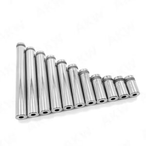
فواصل الكابلات الوسيطة can also contribute to deflection control by maintaining consistent cable alignment along the run, which matters when post-to-post variation in cable path allows individual cables to sag more than the design assumes.
Responsibility for the Compliance Assumptions
When a hardware supplier, a licensed engineer, and an installing contractor each contribute to a cable railing system, the compliance assumptions they use do not automatically align. The supplier may test components to ASTM E935 criteria. The engineer may size posts and anchors based on stated cable tension values. The installer may set tension by feel or by a standard tool setting without verifying the actual force applied. The result is a system where each party believed the others had handled a critical variable, and where no one has explicitly verified the installed assembly against the 4-inch sphere and 50-pound load thresholds together.
IBC Chapter 10 evaluates the guard as a complete assembly, not as a set of individually compliant components. A post that meets a specified section modulus and a cable that meets a specified break strength do not together guarantee that the installed system will pass the sphere test under load. That outcome depends on how the components interact at the actual post spacing, with the actual cable tension, under the load condition that triggers the test.
For custom-built or site-specific systems, the practical norm is that the installer or contractor carries responsibility for confirming the design meets the applicable code requirements as built—including post strength, anchor pullout capacity, and the deflection behavior that results from the specific layout. That is not a formal code assignment; IBC Chapter 10 specifies the performance outcome, not who bears the liability when it is not met. But when a post-acceptance inspection finds a failure, the question of who verified the installed system’s compliance before handover becomes a project record issue, not just a technical one. For additional background on how IRC and IBC requirements differ by occupancy type, the IRC vs IBC cable railing compliance checklist covers the key distinctions.
Documented System Check Before Acceptance
A documented pre-acceptance check closes the gap between assumed compliance and verified compliance. The specific method matters less than the principle: someone needs to apply a representative load to the installed system, confirm that the 4-inch sphere cannot pass through any opening under that load, and record the result before the project is accepted.
One practical field approach involves hanging a 50-pound weight at mid-span of a typical 4-foot post bay and checking whether a 4-inch sphere can pass through any resulting opening. This is not a code-mandated test procedure, but it is a defensible adaptation of the performance criteria the code requires. It surfaces deflection behavior that a static measurement will not reveal, and it generates a record that answers the compliance question the inspector will ask.
The documentation piece is equally important. A system check that produces no written record is difficult to defend if a re-inspection occurs or if responsibility for a post-acceptance finding becomes contested. What needs to be captured is the code basis the design used, the performance thresholds that were checked, the method applied, and the result.
| Documentation Requirement | الغرض | How to Satisfy / Field Verification |
|---|---|---|
| Project code basis | تأكد من أن التصميم استند إلى الإصدار الصحيح من الكود ومعايير الأداء. | توثيق القوانين المعمول بها (مثل IRC/IBC) والاختبارات المطلوبة: قاعدة الكرة ذات القطر 4 بوصات ومقاومة الحمل المركّز البالغ 50 رطلاً. |
| اختبار انحراف النظام المركب | تأكد من أن النظام كما تم تنفيذه يمنع مرور الكرة في ظل أحمال تمثيلية. | قم بإجراء فحص ميداني: ضع وزنًا قدره 50 رطلاً في منتصف امتداد حجرة عمود نموذجية بطول 4 أقدام، وتأكد من أن كرة قطرها 4 بوصات لا يمكنها المرور عبر أي فتحة. |
تخدم الوثائق والفحص الميداني غايات مختلفة: فالأول يؤكد أن التصميم قد تم تنفيذه وفقًا للمعايير الصحيحة، بينما يؤكد الثاني أن النظام المنفذ يعمل بالفعل وفقًا لتلك المعايير. وكلاهما ضروري، وغياب أي منهما يؤدي إلى وجود ثغرة يمكن أن يكشفها الفحص الميداني.
لا تكمن المخاطر الرئيسية المتعلقة بالامتثال في درابزينات الكابلات في وجود مواصفات ناقصة، بل في وجود خطوة تحقق لا يتولى مسؤوليتها أي طرف بشكل صريح. فالمسافات الاسمية، وأحجام الدعامات، وقيم الشد هي مدخلات التصميم. أما الكرة التي يبلغ قطرها 4 بوصات تحت الحمل فهي معيار القبول. وبين هاتين النقطتين يوجد سلوك الانحراف الذي يعتمد على أداء النظام بأكمله ككل، وليس على مدى استيفاء كل مكون لمواصفاته الفردية.
قبل قبول النظام، تأكد من أن كلًا من أساس التصميم واختبار النظام المركب قد تم توثيقهما، وأن الفحص الميداني قد أُجري في ظل تباعد بين الأعمدة وحالة تحميل تمثلان التخطيط الفعلي، وأن الشد المطبق على كل كابل يمكن حسابه وفقًا لتثبيت الأعمدة الطرفية المحدد. وإذا كان أي من هذه العناصر موجودًا فقط كافتراض مشترك بين الأطراف بدلاً من كونه نتيجة مسجلة، فإن ملف الامتثال يعتبر غير مكتمل بغض النظر عن قياسات الأبعاد الساكنة.
الأسئلة الشائعة
س: أقوم بتركيب مجموعة درابزين كبلية جاهزة الصنع، ويقول المصنع إنها متوافقة مع المعايير. فهل ما زلت بحاجة إلى إجراء اختبار ميداني؟
ج: نعم، لأن «كود» (Code) يُقيّم نظام «غارد» (Guard) باعتباره تجميعًا كاملاً ومُركَّبًا، وليس المكونات بمفردها. وقد يفترض تقرير الاختبار الصادر عن الشركة المصنعة شروطًا محددة تتعلق بمسافات الأعمدة والتثبيت والشد، والتي قد تختلف عن ظروف التركيب في موقعك. ويؤكد الفحص الميداني أن النظام كما هو مُنفَّذ يفي بعتبات الكرة ذات القطر 4 بوصات والحمل البالغ 50 رطلاً في ظل متغيرات التركيب الفعلية.
س: بعد قراءة هذا، ما هي المستندات المحددة التي يجب عليّ إعدادها قبل الفحص النهائي؟
ج: قم بإعداد سجل يتضمن معيار الكود المعمول به، وعتبات الأداء التي تم فحصها (حجم الكرة والحمل)، وطريقة الفحص الميداني المستخدمة، والمسافة بين الأعمدة وشد الكابل المطبق، ونتيجة النجاح أو الفشل. وهذا يربط افتراضات التصميم بالأداء المثبت بعد التركيب، ويوفر للمفتش سجلاً واضحاً للامتثال.
س: ماذا لو تطلب تصميمي تباعدًا بين الأعمدة يزيد عن 4 أقدام — هل يمكنني تعويض ذلك بزيادة الشد أو باستخدام كابل أكثر سمكًا؟
ج: في معظم الحالات، يؤدي تجاوز مسافة 4 أقدام بين المراكز إلى زيادة حادة في انحراف منتصف الامتداد عند إجراء اختبار الحمل بوزن 50 رطلاً، ولا يمكن لشد الكابل أو قطره وحدهما التعويض بشكل موثوق للحفاظ على الفتحات ضمن الحد الكروي. ويؤدي استخدام كابل أثقل أو زيادة الشد إلى تقليل بعض الحركة، لكن صلابة الدعامات تصبح العامل المقيد الرئيسي في الامتدادات الأكبر. ويجب التحقق من صحة أي تخطيط يتجاوز مسافة 4 أقدام بين المراكز من خلال إجراء اختبار حمل تمثيلي قبل قبوله.
س: كيف يمكنني الاختيار بين إضافة المزيد من صفوف الكابلات أو الترقية إلى أعمدة أكثر صلابة، في حين أن كلا الخيارين ممكنان من الناحية الهيكلية؟
ج: حدد العائق المقيد لمشروعك. إذا كانت الطبقة التحتية للشرفة أو عمق تثبيت المراسي يحدان من قدرة مقاومة الانسحاب للعمود الطرفي، فإن إضافة صفوف من الكابلات قد تتجاوز هذا الحد الخاص بالمراسي، مما يجعل استخدام أعمدة أكثر صلابة أو تباعدًا وسيطًا أقرب هو الخيار الأفضل. أما إذا كانت المتطلبات المعمارية تقيد ظهور التجهيزات أو عدد الأعمدة، فقد تكون إضافة صفوف من الكابلات هي الخيار الوحيد — ولكن يجب عليك إعادة التحقق من تثبيت العمود الطرفي في ضوء القوة التراكمية الأعلى للكابلات.
سؤال: هل اختبار الانحراف في منتصف المسافة بوزن 50 رطلاً ضروري حقًّا لحاجز شرفة سكنية قصير يبلغ ارتفاعه 3 أقدام؟
ج: نعم. يعتمد الامتثال على الأداء الفعلي للتركيب، وليس على حجم المشروع. فحتى الحاجز الصغير يجب أن يمنع كرة قطرها 4 بوصات من المرور من تحته تحت الحمل. ويكشف الاختبار الميداني السريع عن الانحراف الذي قد يغفل عنه القياس الثابت، كما أنه أرخص بكثير من تكلفة إعادة العمل المطلوبة في حال اكتشف المفتش وجود عيب بعد التسليم.