Most wire railing layouts fail at the detail stage, not the concept stage. A designer draws evenly spaced horizontal lines, the drawing looks clean, and no one flags a problem until a fabricator starts drilling or an inspector measures corner gaps. By that point, post locations are fixed, and correcting a spacing violation means repositioning hardware that was already installed. The decisions that prevent this — cable count, terminal placement, corner strategy, routing method, and post stiffness — have to be locked in before any holes are drilled, not resolved during the first site visit. What follows will help you identify which variables your fabricator needs to confirm before fabrication starts and which omissions create the most expensive rework.
Cable count and terminal positions that govern the layout
Cable spacing is a code-driven geometry problem before it is an aesthetic one. Under the International Building Code, the maximum gap between cables must prevent the passage of a 4-inch sphere. That single threshold is the planning criterion that determines both the maximum allowable spacing between cables and the minimum number of cables required for any given railing height. Treating it as a visual guideline rather than a dimensional constraint is where most early-stage errors originate.
The practical implication is that cable count should be calculated from the 4-inch sphere rule and the finished rail height, then confirmed against the post spacing and cable angle before any layout is drawn. On a standard 42-inch residential guardrail with horizontal cables, the number of cables needed to maintain compliant gaps is higher than many designers assume when first sketching the run. When cables run at even a slight angle — common on stair sections — the apparent vertical gap between cables increases, which may require adding cables beyond what a straight horizontal run would need at the same spacing.
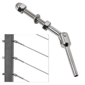
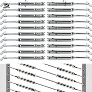
Terminal positions matter because they define where the cable begins and ends its load path. A terminal that is set too close to a corner, or positioned without accounting for the hardware body length, can create a gap at the end condition that exceeds the 4-inch threshold even when the field spacing is correct. Fabricators need to receive a layout drawing that specifies cable count, center-to-center spacing, and the exact terminal position at each post — not just a schematic showing lines. When that level of detail is absent from the drawing, the fabricator fills in the gaps, and those assumptions become the railing you inspect on site.
Spacing errors seen at corners and end conditions
Corners are where compliant field spacing most reliably breaks down. The reason is geometric: a cable that terminates at an angled post, or that passes through a post positioned on the corner apex, subtends a wider apparent gap at the angle than it does along the straight run. That gap may not register on a flat elevation drawing but becomes visible — and measurable — in three dimensions on site.
Two practitioner strategies address this consistently. The first places a single post directly on the corner so cables terminate there, which keeps the run clean but requires verifying that the angled alignment does not create oversized gaps when the 4-inch sphere is applied at the terminal. The second uses a double-post arrangement near the corner with cables offset by half an inch to maintain a uniform grid through the turn. Neither approach is universally correct — the right choice depends on the corner angle, the cable tension path, and the number of runs converging at that point.
| Corner Strategy | Описание | Ключевое соображение |
|---|---|---|
| Post directly on corner | Single post located at the apex of the corner; cables terminate at that post. | Check that spacing at the corner terminal complies with the 4-inch sphere rule, as angled alignment may create larger gaps. |
| Double-post with ½-inch offset | Two posts placed near the corner; cables are offset by ½ inch to maintain a uniform grid. | Keeps cable spacing consistent but increases the number of posts and may influence overall frame rigidity. |
The downstream risk of leaving this unresolved is not only a failed inspection. When a spacing violation at a corner is discovered after fabrication, the remediation options are constrained by the hardware already installed. Adding a cable requires an available terminal point. Moving a post requires redrilling the base plate. In most cases, the least disruptive fix is also the most visible one — a retrofit fitting or a secondary cable that does not match the original run. Pressure-testing the corner strategy during design review, before drilling, is substantially cheaper than correcting it afterward.
Gate conditions carry a version of the same problem. The opening created by a gate interrupts the cable run, and the post at the latch side functions as a terminal. If that terminal position is not designed to maintain the same spacing as the field run, the gap at the gate frame will be wider than the rest of the railing — a common inspection finding on residential decks that were not detailed for code compliance at every condition, only at the typical section.
Through-post routing versus face-fixed fitting tradeoffs
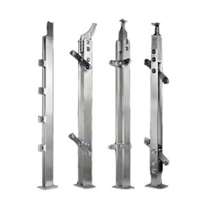
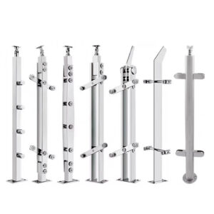
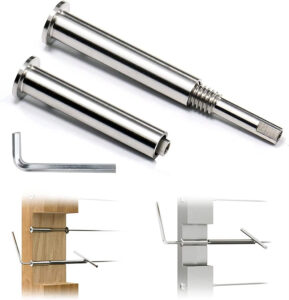
Through-post routing runs cables through drilled holes in each intermediate post, terminating only at the end posts. Face-fixed fittings attach hardware to the post face, allowing cables to terminate at any post without drilling through it. The appearance difference is real: through-post routing produces a cleaner, more linear profile because the hardware is concealed inside the post. But the procurement and installation tradeoffs are significant enough that the appearance benefit should not be the deciding factor.
The core engineering constraint with through-post routing is drilling alignment. Every hole in every intermediate post must be drilled on a consistent centerline so that the cable runs straight through the run without deflecting at each post. In a short straight run with two or three intermediate posts, this is manageable. In a long run with many posts, or a run that changes direction, cumulative misalignment across all the drilled holes becomes a real fabrication risk. A small angular error in one post is invisible in isolation. Across eight or ten posts, the cable path shows a visible bow or kink, and the only correction is re-drilling or reordering posts — both of which are expensive after the run is assembled.
For contractors evaluating cable pass-through fittings, the practical question is not which product looks better but whether the fabrication setup can maintain the drilling precision required to keep alignment consistent across the full run. That requires a jig or fixture approach, not manual hole-by-hole layout. If a fabricator cannot describe their alignment process before drilling starts, through-post routing is a higher-risk choice than the clean appearance suggests.
Face-fixed fittings are more forgiving of post-to-post variation because the fitting adjusts position on the post face rather than requiring a precise through-hole. They also simplify cable replacement: a cable that needs to be replaced in a face-fixed system requires accessing the terminal hardware at the end post, not threading a new cable through a series of drilled holes. In a commercial installation where cables may need periodic tension adjustment or replacement over the building’s service life, that difference in access is a maintenance consideration worth pricing at procurement, not after installation.
Tolerance buildup across repeated drilled holes
Drilling tolerance across a multi-post run is the failure mode buyers most consistently underestimate at the procurement stage. Each individual hole can be within an acceptable positional tolerance and the run can still produce a visually problematic layout, because the errors accumulate in the same direction rather than canceling out. This is not a theoretical concern — it is a predictable outcome of real-world fabrication when the drilling setup is not controlled at the system level.
The variables that compound are hole centerline position, post plumb, and post spacing. If post spacing varies by a small amount across a run — which is normal in field installation, especially on wood or concrete substrates — the cable path between posts will not be a straight line unless the drilling compensates for that variation. It rarely does, because the holes are drilled during shop fabrication before the field conditions are fully known. The result is a cable that appears straight from one end but shows subtle misalignment when viewed along the run, which is how most inspectors and building owners view a finished railing.
The practical check at the design and procurement stage is to ask the fabricator how they control hole centerline position across a full run and what tolerance stack they assume when laying out the drill pattern. A fabricator who specifies a jig-drilled process referenced to a common datum across all posts is managing this risk. A fabricator who marks holes individually post by post is accumulating tolerance without a correction mechanism. That process difference is not always visible in a product quote but shows up in the installed result.
It is also worth noting that tolerance buildup affects more than appearance. A cable that deflects at intermediate posts due to misaligned holes creates a local stress concentration that changes how tension is distributed across the run. The cable is not carrying load the way the design intended, and the terminal hardware at the end posts may be loaded asymmetrically as a result. This is a structural behavior concern, not only an aesthetic one, and it is worth raising before hardware is specified.
Support stability needed for a cleaner wire design
Post stiffness is the threshold most buyers treat as a structural engineering problem and ignore at the procurement and layout stage. That sequencing creates a practical risk: if the frame cannot hold the cable geometry stable under installation loads and wind or impact loads in service, the layout precision achieved during fabrication will not be maintained in the finished installation.
Cable tension loads posts laterally. A post that deflects under that lateral load allows the cable to sag or shift, which changes the apparent spacing between cables and can create gaps that were not present in the fabricated assembly. As a design planning criterion, posts in cable railing systems are typically expected to resist line loads in the range of 0.5 to 1.0 kN/m to maintain cable geometry stability — a figure drawn from structural cable system practice in building contexts and useful as a planning benchmark, though the applicable local standard should always govern for any specific project. For reference on how structural cable behavior interacts with support framing in building applications, GB/T 43485-2023 provides relevant technical background on full locked cable systems for building structures.
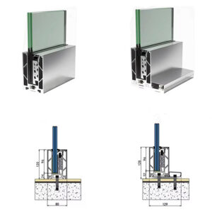
Post material, wall thickness, and base connection all contribute to lateral stiffness. A hollow section post with thin walls and a surface-mounted base plate will deflect more under cable tension than a heavier section with a welded or grouted base. When post stiffness is borderline, installers often respond by reducing cable tension to limit deflection — which then produces a visible cable sag in the field and a spacing condition that no longer matches the design. The fabricator and the structural frame specification need to be coordinated before the cable layout is finalized, not after the posts are installed and the tension targets become a negotiation.
For projects where the post spacing is long or the cable run changes direction, intermediate posts take on a larger share of the lateral load. Those posts need to be evaluated against the actual cable tension and run geometry, not assumed to match the standard section used at terminal posts. Through-post cable hardware for intermediate posts carries different load transfer requirements than terminal hardware, and specifying the same section for both conditions often underestimates what intermediate posts need to do.
A frame that holds the cable geometry through installation and service conditions is the foundation that makes a clean cable layout achievable. Buyers who confirm post stiffness before layout is finalized have a much more predictable fabrication and inspection outcome than those who treat it as a field adjustment.
The most productive use of a pre-fabrication review is to pressure-test the fabricator’s approach to the four variables that determine whether the installed railing matches the design: corner detailing, terminal positions, drilling tolerance control, and post stiffness. These are not aesthetic preferences — they are the geometric and structural conditions that determine whether cable spacing passes inspection at every condition, not just at the typical section in the middle of a straight run.
Before any holes are drilled, confirm that the layout drawing specifies cable count, center-to-center spacing, and terminal hardware position at every post — including corners, gates, and end conditions. Confirm that the fabricator uses a controlled drilling process referenced to a common centerline datum. And confirm that the post section and base connection are adequate for the cable tension loads the run will impose. If any of those three questions does not have a clear answer from the fabricator, that is the point to resolve it — not after the first run is installed and the spacing is already measured.
Часто задаваемые вопросы
Q: Does this spacing and layout guidance still apply if the balcony railing runs on a sloped or stair section rather than a level deck?
A: The same code threshold applies, but stair sections require a higher cable count than a level run at identical post spacing. When cables run at an angle, the apparent vertical gap between them increases, which means a spacing that passes the 4-inch sphere test on a horizontal run may fail on the stair section. Cable count and terminal positions should be recalculated separately for each stair run, not copied from the level balcony layout.
Q: Once the layout drawing is finalized and the fabricator confirms the drilling process, what should happen before a purchase order is placed?
A: The structural frame specification should be confirmed against the cable tension loads before procurement is committed. Post section, wall thickness, and base connection details need to be evaluated against the actual run geometry and intermediate post load conditions before hardware is ordered. Discovering that a post section is undersized after the frame is installed forces a choice between reducing cable tension and accepting visible sag, or replacing structural members — both of which are more expensive than coordinating the frame specification at the design stage.
Q: At what run length or post count does through-post routing become too risky to justify the appearance benefit?
A: There is no fixed post count, but the risk increases faster than most buyers expect once a run exceeds five or six intermediate posts, a change of direction is involved, or the substrate introduces unpredictable field spacing variation. The controlling factor is whether the fabricator uses a jig-drilled process referenced to a common datum across all posts. Without that process control, the tolerance stack across a long run reliably produces visible misalignment regardless of how carefully each individual hole is marked. If the fabricator cannot describe a systematic alignment method, the run length at which through-post routing becomes problematic is shorter than the product appearance implies.
Q: How does the choice between through-post routing and face-fixed fittings affect long-term maintenance cost, not just upfront installation?
A: Face-fixed fittings carry a lower maintenance cost in most commercial installations because cable replacement requires accessing terminal hardware at end posts rather than threading a new cable through a series of drilled intermediate holes. Over a building’s service life, cables may need tension adjustment or full replacement, and the labor difference between the two systems becomes material at that point. Through-post routing is not inherently the wrong choice, but the cleaner appearance at installation comes with a higher replacement labor cost that should be priced at procurement rather than discovered when the first cable needs to be changed.
Q: Does a wire railing on a low-occupancy residential balcony actually need the same level of pre-fabrication review as a commercial project?
A: Yes, because the failure modes are geometric, not occupancy-dependent. The 4-inch sphere spacing rule, corner gap conditions, and tolerance buildup across drilled holes produce the same inspection problems on a residential balcony as on a commercial installation. The cost of rework after fabrication scales with run length and complexity, not with how many people use the space. Residential projects are more likely to skip pre-fabrication review precisely because the stakes feel lower — which is also why spacing violations at corners and gate conditions show up more often on residential decks than on commercial projects with formal submittal processes.