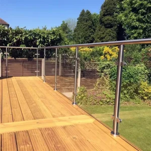
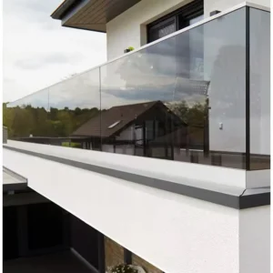
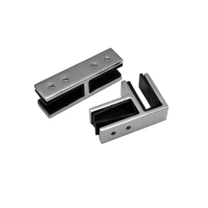
Plan the whole route before choosing rail lengths
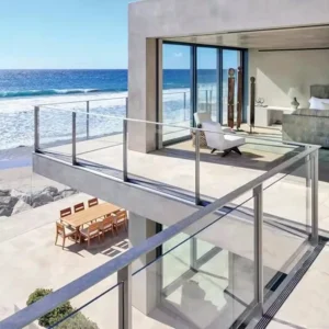
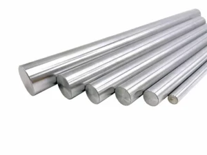
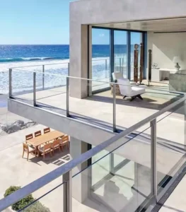
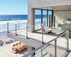
A continuous cap rail system creates one coordinated top line across multiple glass panels or supports. The buying task is route planning: select the profile and interface, place supports and splices, resolve corners and terminals, allow movement, and decide what is shop-prepared versus cut on site. “Continuous” describes the finished visual and functional route; it does not promise one unbroken shipping length or a joint-free installation.
Send a plan or elevation with total runs, corners, slopes, ends and approximate glass/support positions. A budget review can start before every dimension is final, but fabrication should use an approved route and cut schedule.
A continuous system is more than a single cap rail assembly
A single cap rail assembly can solve one glass edge and its nearby accessories. A continuous system must keep profile alignment and interface continuity across several transport lengths, panel joints, corners, changes of direction and building movement breaks. It also needs a component schedule that distinguishes the rail from the supports below it.
| Route | Interface to freeze | System boundary |
|---|---|---|
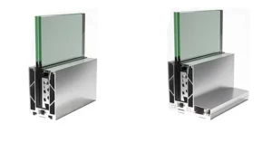
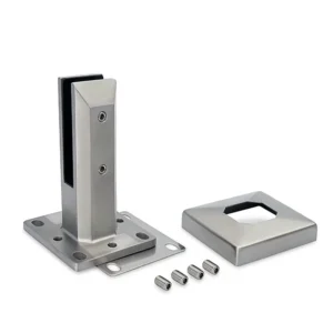
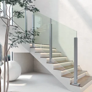
| Glass-top rail | Glass build-up, open slot, dry insert or bonding route, panel joints and edge clearance. | Base shoe, standoffs, posts, glass and anchors are separate unless expressly listed. |
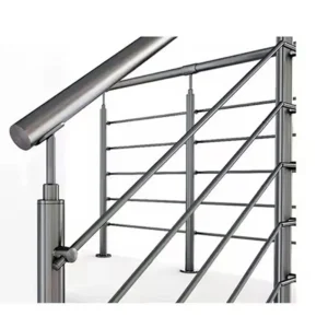
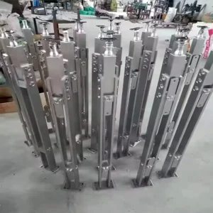
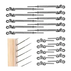
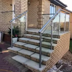
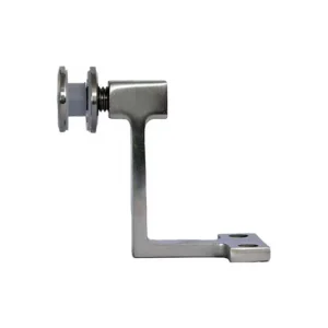
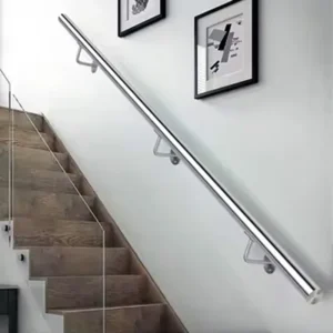
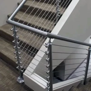
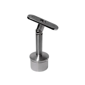
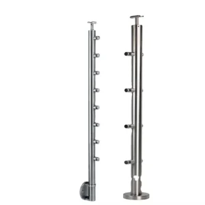
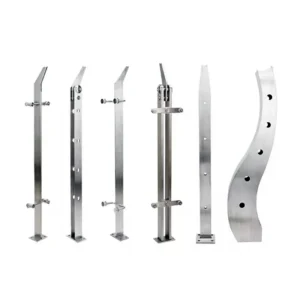
| Post- or bracket-supported rail | Saddle/adapter geometry, support grid, fasteners, rail wall and joint relation. | Posts, brackets and substrate anchors need their own defined supply and engineering responsibility. |
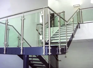
| Hybrid route | Where support changes between glass, posts, walls or independent brackets. | Every transition needs a detailed connector and load path; similar outside shapes are not enough. |
Match profile, opening and support route
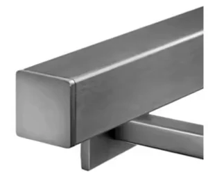
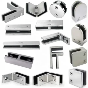
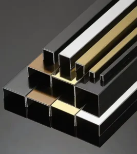
Round, oval and rectangular forms change sightlines, corners, connector sleeves and hand-contact geometry. For a glass-top route, the internal opening must also match the full glass build-up and the chosen insert or bonding detail. For a supported rail, the underside or internal cavity must accept the selected saddle, adapter or connector without weakening the profile or interfering with the finish.

- Shape and size: state the required external profile and the critical internal interface dimensions.
- Glass or support: identify every point where the rail bears on glass, a post, a bracket or a wall return.
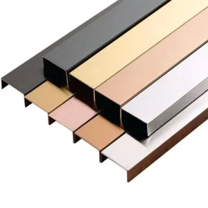
- Surface: provide finish name, colour reference or sample approval; a photograph is not a finish standard.
- Окружающая среда: provide interior/exterior exposure, coastal or pool conditions, cleaning chemicals and maintenance access so the proposed material/finish can be compared on the same basis.
Treat every splice, corner and terminal as part of the route
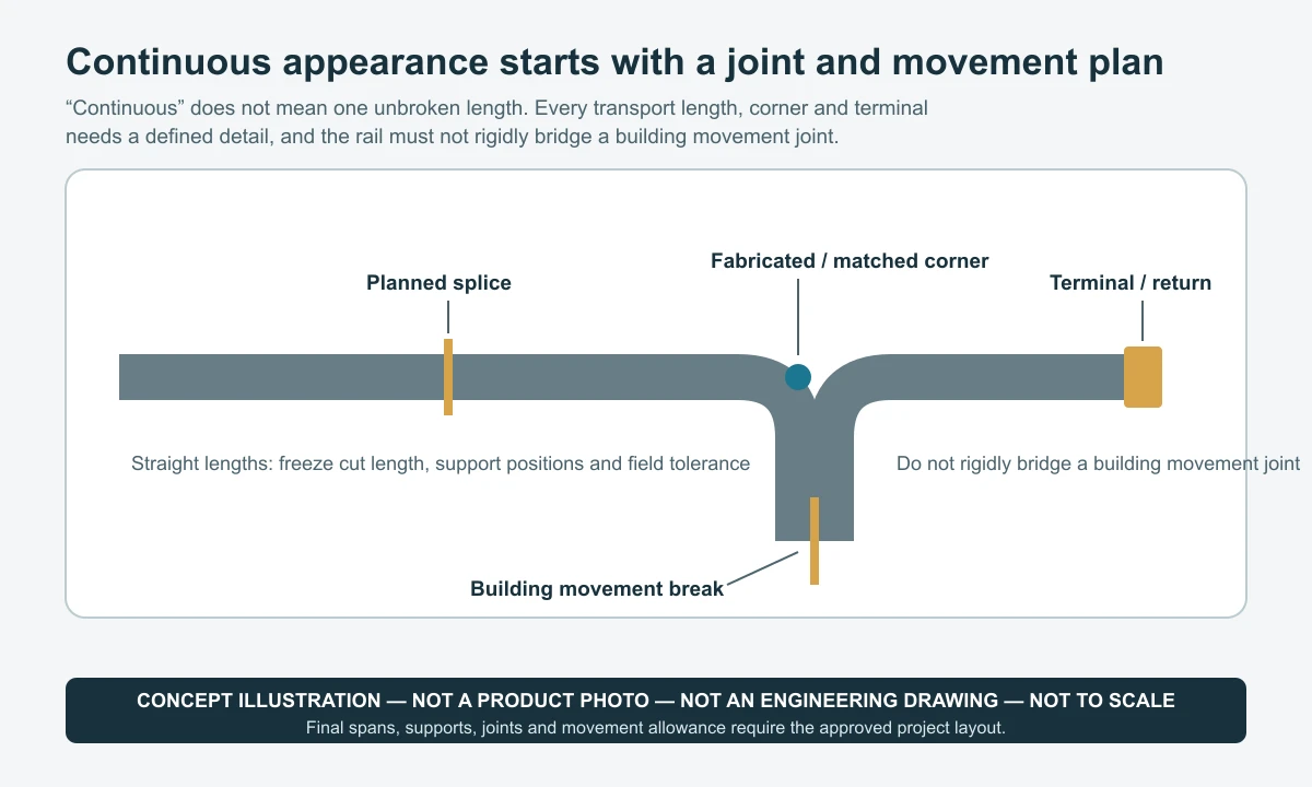
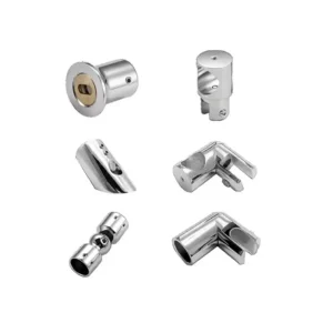
Place joints where they can be assembled, inspected and kept visually consistent. Avoid landing a splice directly over an incompatible glass joint, bracket or bend unless the selected detail is designed for that condition. A connector sleeve may align two sections but does not automatically provide structural continuity or accommodate expansion.
- Straight splices: record rail section, connector engagement, bonding or fixing method and finish alignment.
- Horizontal corners: choose a fabricated corner, matched fitting or approved field mitre; do not force a straight sleeve to perform as a corner.
- Slopes and stair transitions: show plan angle and vertical angle separately, including the handed orientation.
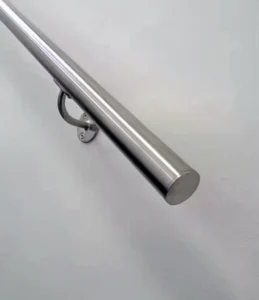
- Terminals: distinguish a decorative end cap from a wall return or stabilizing connection that has a load-transfer duty.
- Building joints: stop or transition the rail so that the approved movement joint can function.
Define support and continuity without transferring system claims to the rail
The project engineer should state whether the continuous rail is decorative edge protection, a graspable handrail, a required top rail or part of the guard load path. That decision controls the allowable spans, support positions, connector treatment and terminal details. The rail profile alone cannot establish the capacity of glass panels, posts, brackets, base shoes, anchors or substrate.
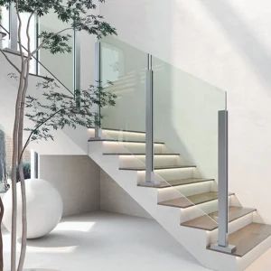
For glass-top runs, show the glass panel sequence and base/support system below. For post- or bracket-supported runs, show the support grid and every change in substrate. At transitions, confirm which component maintains alignment and which transfers load. If two suppliers divide the rail and supports, the interface dimensions and responsibility must be explicit on both quotations.
Keep water and thermal movement from becoming hidden joint problems
Exterior cap rail joints can admit water. The approved detail should identify which joints are sealed, where water can leave, how cut edges are treated and whether an insert or bonding bed could trap moisture. At terminals and low points, keep drainage and cleaning access clear instead of sealing every void as a closed chamber.
Metal lengths, glass panels and the supporting building move at different rates. For long routes, provide expected temperature conditions, building joints and fixed/sliding support logic. Do not rigidly bridge a building movement joint. The proposal may identify supplied splice or expansion components, but project-specific movement allowance and placement remain part of the approved engineering detail.
Choose a cut strategy that fits transport and site tolerance
A continuous appearance can be achieved with coordinated manageable lengths. Shop-cut sections improve repeatability when the survey and support positions are stable. Oversize lengths for site trimming can absorb verified tolerance but require protected storage, correct tooling, deburring, cleaning and finish repair.
Before release, issue a schedule for every piece:
- piece mark, finished length, orientation and location on the elevation;
- square cut, mitre, bend or transition geometry;
- factory-installed and loose-supplied sleeves, corners, inserts, caps and adapters;
- pre-drilled holes or slots, with datum and relation to supports;
- field-cut allowance and the method for protecting exposed cuts and visible finishes;
- packing sequence so installers can unload by route rather than opening every bundle.
Field welding, grinding or drilling after final finishing can alter alignment and appearance. If it is unavoidable, assign the repair and inspection method before ordering.
Make the system package visible on one component schedule
| Package line | Fields the quotation should return | Common unlisted boundary |
|---|---|---|
| Rail lengths | Exact section, proposed material/finish, piece lengths and preparation | Installed capacity, field labour and every possible profile |
| Glass interface | Insert or bonding route, exact glass build-up and supplied consumables | Glass, sealant approval, base shoe or standoffs |
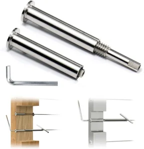
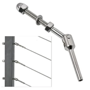
| Support interface | Saddles/adapters, fasteners, support locations and preparation | Posts, wall brackets, anchors or substrate unless listed |
| Route accessories | Straight joiners, corners, slope transitions, returns, end caps and movement pieces | Structural continuity or movement capacity unless documented |
| Complete railing | Glass, supports, anchors, calculations, installation and inspection only if expressly included | Automatically included by the word “system” |
Send route data that produces a comparable proposal
For a first review, send a plan/elevation, approximate total length, number and type of corners, slopes and terminals, preferred visible profile, glass-top or support-mounted route, known glass build-up, project exposure and estimated quantity. Before production, add surveyed dimensions, approved support/load-path detail, glass and interface tolerances, joint and movement plan, support positions, cut/hole schedule, finish sample requirement and factory-versus-field work split.
The returned proposal should identify the exact rail section, proposed material and finish, piece lengths, glass/support interface, included connectors/corners/returns/end caps, supplied consumables, fabrication, packing, exclusions and the drawings, samples or engineering approvals still required. That information lets you compare complete route responsibility rather than only price per length.