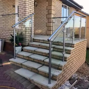
For architects, builders, and property owners, specifying a stainless steel cable railing for an outdoor stair system presents a unique technical challenge. The combination of angled runs, high visibility, and critical safety functions demands more than just aesthetic consideration. The core decision hinges on navigating a complex web of building codes, structural engineering, and material science to ensure a system that is not only visually striking but also permanently safe and compliant. Misconceptions about simple installation or universal product applicability can lead to costly failures and liability exposure.
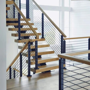
This focus is essential now, as modern design trends increasingly favor cable railings for their clean lines and unobstructed views. However, this popularity has also highlighted a knowledge gap between design intent and practical, code-compliant execution. Understanding the precise requirements for spacing, tension, and structural performance is non-negotiable for any professional responsible for the safety and longevity of an outdoor stair project.
Key Building Codes for Stair Cable Rail Systems
Defining the Regulatory Framework
The foundation of any safe installation is the governing building code, which varies by project type. For residential stairs, the International Residential Code (IRC) typically applies, while commercial projects fall under the International Building Code (IBC). A critical first step is always verifying local amendments, as these take precedence. These codes mandate a guardrail wherever a fall of over 30 inches is possible, with minimum heights of 36 inches (IRC) or 42 inches (IBC) measured vertically from the stair nosing. Additionally, a graspable handrail is required on any stair with four or more risers.
Distinguishing Between Guard and Handrail Functions
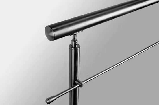
Professionals must understand that the code treats the guard (the barrier) and the handrail (the graspable component) as distinct elements, though they can be integrated. A top rail can serve both functions if its profile meets specific graspability requirements. This distinction drives product engineering, as manufacturers must design systems where the top rail satisfies handrail criteria while the entire assembly meets guard load requirements. From my experience specifying these systems, this dual-purpose design is a key differentiator for products intended for stair applications, as it simplifies compliance.
The Role of Certified Documentation
This regulatory framework transforms code from a checklist into a driver of specific product selection. Manufacturers engineer entire systems—posts, cables, fittings—to meet mandated safety parameters. Consequently, third-party testing documentation and comprehensive warranties are not just marketing materials; they are critical for liability mitigation and trust. They provide verifiable proof that the assembled system performs as required, which is essential for securing permits and satisfying commercial project specifications.
Code Requirements at a Glance
The following table summarizes the primary code triggers and requirements that govern stair cable rail design, providing a quick reference for project planning.
| Code / Application | Minimum Guard Height | Key Requirement |
|---|---|---|
| IRC (Residential) | 36 inches | 30-inch fall trigger |
| IBC (Commercial) | 42 inches | 30-inch fall trigger |
| All Applications | 4-inch sphere rule | Maximum opening size |
| Stairs with 4+ Risers | N/A | Graspable handrail required |
Source: ICC IRC Section R312 Guards and Handrails. This code section establishes the minimum guard height of 36 inches for residential stairs and the requirement for a handrail on stairs with four or more risers, forming the baseline for compliant cable rail design.
The 4-Inch Sphere Rule: Spacing and Deflection Explained
The Core Safety Provision
The 4-inch sphere rule is the definitive safety provision governing cable spacing. It states that a 4-inch diameter sphere cannot pass through any opening in the guard infill. To ensure compliance after accounting for inevitable cable deflection under load or over time, the nominal engineered spacing must be less than 4 inches. A standard, compliant center-to-center spacing is 3 inches or 3 1/8 inches. This precise measurement is a calculated safety margin, not an aesthetic choice. Installing cables at a true 4-inch spacing will almost certainly fail the sphere test once deflection occurs.
Special Considerations for Stair Geometry
For stair guards, an additional geometric requirement exists. The infill must also prevent a 4 3/8-inch sphere from passing through the triangular space formed by the stair tread, riser, and the bottom rail. This often necessitates a specific bottom rail height or a specialized filler solution. A significant strategic implication is the jurisdictional wildcard of the “ladder effect,” where some local codes amend model rules to ban horizontal cables entirely over climbability concerns. This creates a regulatory patchwork that demands local verification before design finalization.
Engineered Spacing for Real-World Performance
The relationship between nominal spacing, deflection, and the test sphere is a fundamental engineering parameter. The following table breaks down the key specifications that ensure a system meets the intent of the code under real-world conditions.
| Parameter | Specification | Purpose |
|---|---|---|
| Nominal Cable Spacing | 3 to 3 1/8 inches | Safety margin for deflection |
| Test Sphere Diameter | 4 inches | Maximum allowable opening |
| Triangular Stair Gap | Blocks 4 3/8-inch sphere | Prevents passage at tread |
| “Ladder Effect” Bans | Local code amendments | Horizontal cable prohibition |
Source: ICC IRC Section R312 Guards and Handrails. This code defines the requirement that guards shall not have openings that allow passage of a 4-inch sphere, which directly governs the engineered spacing of cable railing systems.
Structural Load Requirements for Safe Stair Railings
Defining the Performance Benchmarks
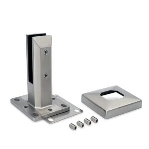
Code compliance requires the entire railing system to withstand specific structural loads. The top rail must resist a concentrated load of 200 pounds applied in any direction. The cable infill and its attachments must withstand a uniform load of 50 pounds applied over a one-square-foot area. These are not theoretical values but performance benchmarks verified through standardized testing. Meeting them is a function of the complete engineered system—posts, cables, fittings, and anchors—installed precisely per the manufacturer’s specification.
The System Engineering Imperative
Using undersized components or improper fasteners will compromise the system’s strength regardless of cable spacing. The posts must be anchored to resist the overturning moment created by the top rail load. The cable fittings must have a tensile strength far exceeding the cable’s breaking strength. This underscores why warranty and certified testing documentation are critical market differentiators. They provide verifiable proof of performance, which is essential for permitting, commercial projects, and mitigating liability for installers and owners.
Validating System Strength
The load requirements defined by standards like ASTM F2453 provide the measurable criteria for a safe system. The table below outlines the key structural benchmarks that a compliant cable railing system must meet.
| System Component | Required Load Resistance | Application Standard |
|---|---|---|
| Top Rail | 200 pounds concentrated | Any direction |
| Cable Infill | 50 pounds per sq. ft. | One-square-foot area |
| Complete System | As engineered | Posts, fittings, anchors |
| Verification | Third-party testing | Warranty & documentation |
Source: ASTM F2453 Standard Specification for Stainless Steel Cable Systems. This performance specification establishes the structural load requirements, including the 200 lb concentrated load for top rails and the 50 lb/sq. ft. load for infill, that compliant cable systems must withstand.
How to Tension Cable Rail on Stairs: A Step-by-Step Guide
The Non-Negotiable Need for a Gauge
Proper tension is critical for safety and maintaining compliance with the 4-inch rule. Insufficient tension causes sag, creating unsafe openings; over-tensioning stresses posts, causing bowing and potential anchor failure. A systematic, gauge-based approach is mandatory—relying on feel is professionally insufficient. A calibrated tension gauge provides the only objective measurement. Target tension is typically specified by the system engineer, often in the range of 150-250 lbs for 1/8″ diameter cable.
Executing the Correct Tensioning Sequence
The sequence of tensioning is as important as the final tension value. Begin by tensioning the middle cable run to approximately 80% of the target. Then, alternate tensioning cables upwards and downwards from the center, working your way out to the top and bottom runs. This sequence distributes the load evenly across the post, minimizing distortion. On stairs, cables run at an angle, requiring correct orientation of the tensioning hardware to prevent binding. Always perform a final re-tensioning pass 2-3 weeks after installation to account for initial cable settlement and strand seating.
A Methodical Approach to Tension
Following a disciplined process with the right tools ensures consistent, safe results. The table below outlines the key steps and parameters for proper cable tensioning.
| Step | Key Parameter / Tool | Target / Sequence |
|---|---|---|
| Tension Measurement | Calibrated tension gauge | Mandatory, not feel |
| Target Tension (1/8″ cable) | 150-250 lbs | Per system engineer |
| Tensioning Sequence | Middle cable first | Then alternate outwards |
| Final Tension Runs | Top and bottom cables | Last in sequence |
| Post-Installation Re-tension | 2-3 weeks later | Account for settlement |
Source: ASTM F2453 Standard Specification for Stainless Steel Cable Systems. This standard includes requirements for cable tension and system performance to ensure the completed installation maintains safety and complies with the maximum opening requirements under load.
Post Spacing and Design for Angled Stair Applications
The Deflection Control Equation
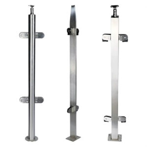
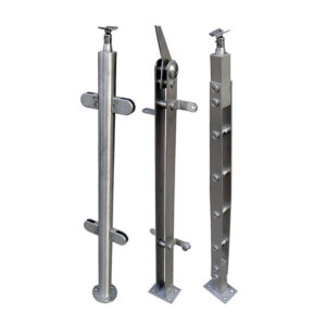
Post spacing is a primary variable controlling cable deflection and overall system rigidity. For metal posts on level runs, a maximum of 4 feet on-center is standard. On staircases, closer spacing—often 3 to 3.5 feet—is frequently recommended. The angled runs increase the effective span between attachment points and subject the posts to more complex loads, increasing deflection risk. This is a key value-engineering consideration: reducing post count to save on material cost can inadvertently increase compliance risk if deflection exceeds the allowable limit.
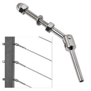
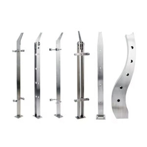
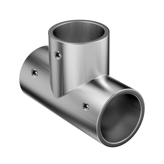
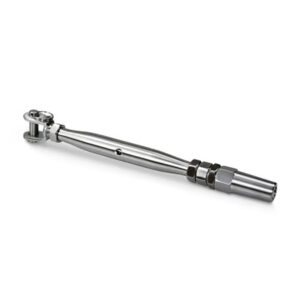
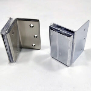
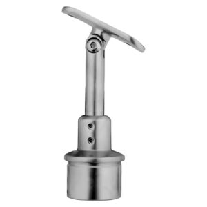
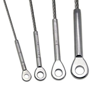
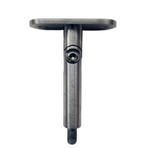
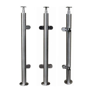
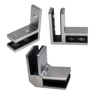
Specialized Components for Slope Alignment
Stair systems demand specialized hardware not always needed on decks. Pre-angled or adjustable stair posts are required to maintain proper vertical alignment of the cable runs along the slope. Transformer fittings at the top of the post are essential for changing the cable direction from the stair angle to a level horizontal run at landings. This inherent complexity creates a distinct market segment. Providers with robust, integrated stair-specific solutions and detailed installation guides command a premium by reducing design and installation risk.
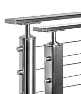
Integrating Form and Function
For projects requiring a cohesive look from deck to stair, selecting a system with compatible components for both level and angled applications is crucial. A unified stair and deck cable railing system ensures material consistency, simplifies sourcing, and often provides engineered solutions for the challenging transition points where the stair meets the landing.
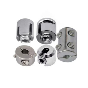
Selecting Materials: Cable, Fittings, and Corrosion Resistance
The Hierarchy of Corrosion Resistance
Material selection follows a clear hierarchy dictated by the environment. Type 316 marine-grade stainless steel is the unequivocal standard for outdoor stairs, especially in coastal or harsh industrial environments, due to its superior resistance to chlorides and pitting corrosion. For general outdoor applications without salt exposure, Type 304 stainless steel offers good performance. Powder-coated aluminum is another option, but its compatibility with stainless cable must be carefully managed. The critical rule is to avoid galvanic corrosion by not mixing incompatible metals.
The Importance of Material Consistency
All system components must match in grade and compatibility. Using 316 stainless cable with 304 fittings, or aluminum posts with carbon steel screws, creates galvanic cells that accelerate corrosion, particularly at connection points. This creates high barriers to entry for coastal markets, which become defensible niches for specialists with fully verified 316 or 2205 duplex stainless systems. Generalist brands risk significant reputational damage from premature failures in aggressive environments.
Specifying for Longevity
Choosing the right material grade is a foundational decision for longevity. The following table provides a clear framework for material selection based on the project environment.
| Environment | Recommended Material Grade | Critical Consideration |
|---|---|---|
| Coastal / Harsh | Type 316 stainless steel | Superior corrosion resistance |
| General Outdoor | 304 stainless steel | Good corrosion resistance |
| All Applications | Matching cable & fittings | Prevent galvanic corrosion |
| High-Performance Niche | 2205 duplex stainless | Specialist market defense |
Source: ASTM A276 Standard Specification for Stainless Steel Bars. This material specification defines the chemical and mechanical properties for stainless steel grades like 304 and 316, ensuring components have the necessary strength and corrosion resistance for long-term outdoor use.
Common Installation Mistakes and How to Avoid Them
Errors Rooted in Code Misinterpretation
Common installation failures often stem from ignoring code nuances. As noted, installing cables at a true 4-inch spacing is a fundamental error that will likely fail inspection. Another is neglecting the triangular opening requirement on stairs. Furthermore, failing to verify local “ladder effect” bans can void an entire project post-installation. These mistakes highlight the need for pre-installation code verification with the local building department, not just reliance on model codes.
Oversights in Process and Components
Improper tensioning without a gauge leads to inconsistent safety and aesthetics. Using non-compliant fittings or fasteners that lack the required structural capacity is a critical oversight that compromises the entire system’s load rating. I’ve seen projects where generic turnbuckles replaced certified tensioning devices, introducing a clear point of failure. The market’s segmentation into DIY, pro-sumer, and professional tiers exists to match system complexity with installer capability. Using a basic DIY kit for a complex commercial stair project is a fundamental mismatch that invites these mistakes.
Maintaining Your Cable Railing System for Long-Term Safety
Proactive Inspection and Adjustment
Maintenance is essential for preserving both safety and aesthetics. Periodically inspect all fittings for tightness and check cable tension, especially after extreme temperature swings which cause metal expansion and contraction. Re-tension as needed using the proper gauge. For coastal installations, rinsing the system with fresh water regularly to remove salt spray deposits is a simple but effective corrosion mitigation strategy. Annually inspect for early signs of corrosion, particularly at connection points and where dissimilar metals may meet.
Preserving Value and Compliance
This proactive upkeep protects the owner’s investment and ensures ongoing code compliance. A loose cable or corroded fitting can compromise the system’s ability to meet the structural load and sphere test requirements. The trend toward integrated accessories like LED lighting transforms the railing into a multifunctional feature, but these additions introduce electrical components that also require specific maintenance checks. This drives long-term engagement with the system, emphasizing value beyond the initial installation.
The decision framework for a stainless steel cable stair railing prioritizes verified compliance, complete system engineering, and environmental durability. First, validate local codes and select a system with third-party certification for structural loads and spacing. Second, specify materials—preferably Type 316 stainless—with full component compatibility for your environment. Third, ensure the installation plan accounts for stair-specific challenges like post spacing, tensioning sequence, and transitional hardware.
Need professional guidance for a code-compliant, high-performance outdoor stair solution? The experts at Esang specialize in engineered cable railing systems designed to meet the exacting demands of both safety and modern architecture. Contact us to discuss your project specifications. You can also reach our team directly at mailto:[email protected] for detailed technical consultation.
Frequently Asked Questions
Q: What is the correct cable spacing to ensure compliance with the 4-inch sphere rule on stairs?
A: To reliably meet the safety requirement, you must engineer the system for a nominal spacing less than 4 inches, typically 3 inches or 3 1/8 inches center-to-center. This accounts for inevitable cable deflection under load or over time. For projects where permitting is critical, you must also verify local amendments, as some jurisdictions ban horizontal cables entirely due to climbability concerns, which can void a standard design.
Q: How do structural load requirements impact the selection of a cable railing system for a commercial stair?
A: The complete system must withstand a 200-pound concentrated load on the top rail and a 50-pound load over one square foot on the cable infill. This performance depends on the engineered interaction of posts, cables, fittings, and anchors installed per specification. For commercial projects, you should prioritize suppliers that provide third-party certified testing documentation, as this verifies performance for permitting and significantly reduces liability exposure.
Q: What is the proper procedure for tensioning cables on an angled stair installation?
A: Use a calibrated tension gauge to achieve the engineer-specified force, typically 150-250 lbs for 1/8″ cable. Begin tensioning the middle cable run, then alternate upwards and downwards from that center point, finishing with the top and bottom runs to distribute load evenly. For stair applications, plan to re-tension the entire system 2-3 weeks after installation to account for initial cable settlement and ensure long-term spacing compliance.
Q: Why is post spacing more critical for stair applications compared to level deck runs?
A: On stairs, closer post spacing—often 3 to 3.5 feet on-center instead of a standard 4 feet—is recommended to control increased cable deflection from angled loads and longer spans. This is a key value-engineering consideration. If your project aims to minimize material costs by maximizing span, you must verify through engineering analysis that the resulting deflection will not cause the system to fail the opening limits specified in IRC Section R312.
Q: Which material specification is essential for cable railings in coastal environments?
A: Type 316 marine-grade stainless steel is the standard for superior corrosion resistance in harsh or salt-air environments. All components, including fittings and fasteners, must match this grade to prevent galvanic corrosion. This creates a defensible niche for specialists; if your project is in a coastal region, you should verify the supplier’s entire system uses 316 or higher-grade stainless to avoid premature failure and reputational damage.
Q: What are the most common installation errors that compromise stair cable rail safety?
A: Critical mistakes include installing cables at a true 4-inch spacing (which fails under deflection), tensioning by feel instead of with a gauge, and using non-compliant fittings that undermine structural load capacity. These errors often stem from using a DIY-grade system for a complex application. For professional installations, your specification should mandate components and procedures that meet the performance criteria of ASTM F2453 to ensure code compliance and safety.
Q: How does maintenance differ for a cable railing system with integrated accessories like LED lighting?
A: Standard maintenance involves periodic tension checks, fitting inspections, and freshwater rinsing in coastal areas. When the system includes integrated electrical or functional accessories, you must also establish specific inspection protocols for those components, such as checking wire connections and seal integrity. This transforms the railing into a multifunctional asset but requires planning for more comprehensive long-term upkeep to protect the total investment.