Designing a cable railing for a 30-foot deck run presents a critical engineering challenge. The primary risk is not the cables themselves, but the unregulated variable of post spacing. Building codes mandate safety outcomes—like the 4-inch sphere rule and specific load capacities—but leave the method of achieving them to the installer. This creates a compliance gap where improper spacing can lead to excessive cable deflection, structural failure, and significant liability. The core decision is balancing span length with system performance to meet code through engineering, not guesswork.
This calculation is paramount now due to increased code enforcement and a market saturated with components of varying quality. A 30-foot span magnifies every engineering compromise. Selecting a spacing based solely on aesthetics or initial cost, without verifying the system’s rated capacity, is a common and costly mistake. The integrity of the entire guard depends on this single calculation, making it the foundational step for any safe, lasting installation.
Understanding the 4-Inch Sphere Rule and Load Requirements
The Non-Negotiable Safety Parameters
Compliance starts with two code-mandated pillars. The first is the 4-inch sphere rule, which prohibits a sphere of that diameter from passing through any guard opening. In practice, this requires installing cables with a tighter spacing, typically 3 to 3.25 inches on-center, to maintain compliance under load as cables deflect. This 20-25% buffer transforms a static measurement into a dynamic performance target.
The second pillar is structural load capacity. Codes require the system to resist a 50 pounds per foot linear load and a 200-pound concentrated load on the top rail. Each cable must also withstand a 50-pound concentrated load. Crucially, while codes prescribe these outcomes, they do not specify maximum post spacing. This omission transfers significant responsibility to the installer to select a system and spacing that demonstrably meets these loads.
The Engineering Gap in Code Compliance
This gap between required performance and prescribed method is where most planning errors occur. The adequacy of your post spacing hinges entirely on the proprietary engineering of your chosen cable system—its cable diameter, tensioning method, and post strength. Relying on generic spacing recommendations without consulting the manufacturer’s certified load tables is a primary risk factor. The code ensures a safe outcome; your spacing and component selection determine the method.
Foundational Code Requirements
The following table outlines the critical safety parameters established by model building codes that every cable railing design must satisfy.
| Code Requirement | Load Specification | Critical Note |
|---|---|---|
| 4-inch sphere rule | Max 4-inch opening | Non-negotiable safety parameter |
| Installed cable spacing | 3 to 3.25 inches on-center | 20-25% buffer for deflection |
| Linear load capacity | 50 pounds per foot | Applied to entire railing system |
| Concentrated load (top rail) | 200 pounds | |
| Concentrated load (cable) | 50 pounds |
Source: ICC IRC Section R312 Guards. This code section mandates the 4-inch sphere rule and specifies the structural load requirements for guards, forming the foundational safety criteria for cable railing design.
Calculating Post Spacing for a 30-Foot Run: Step-by-Step
Establishing Your Maximum Allowable Span
The first step is to determine the maximum span your specific cable system can support while meeting code loads. This is not a universal number. While robust, engineered systems may permit spans up to 8 feet, a conservative and common industry standard for many quality systems is 4 to 6 feet on-center. Always start with the manufacturer’s published maximum allowable span for their components. For a 30-foot run, using a 6-foot maximum span, you divide the total length: 30 feet / 6 feet = 5 sections. The number of posts is always one more than the number of sections, requiring 6 posts spaced 6 feet on-center.
Optimizing for Performance and Feel
A maximum-span calculation often yields a functional but not optimal layout. Reducing the span increases rigidity and reduces cable deflection, creating a sturdier feel. Recalculating for a 5-foot center requires 7 posts (30/5 = 6 sections). For 4-foot centers, you need 9 posts (30/4 = 7.5 sections, rounded to 8, spaced 3.75 feet OC). This reveals the core trade-off: closer spacing increases material and labor costs but enhances performance, simplifies tensioning, and often provides a more robust aesthetic. In my experience, clients who opt for the minimum posts often later notice the increased flex, confirming that this calculation is as much about perceived quality as it is about code.
Post Spacing Calculation Matrix
The table below illustrates how different target spans directly impact the number of posts and final spacing for a standard 30-foot deck run.
| Target Span (ft) | Number of Posts | Resulting Spacing (ft OC) |
|---|---|---|
| 6 (max common) | 6 | 6.0 |
| 5 (recommended) | 7 | 5.0 |
| 4 (sturdy) | 9 | 3.75 |
| 8 (robust systems) | 5 | 7.5 |
Note: Number of posts = (Total Run / Target Span) + 1.
Source: Technical documentation and industry specifications.
The Critical Link Between Post Spacing and Cable Deflection
The Physics of Span and Sag
Post spacing is the primary determinant of cable deflection. A tensioned cable will sag; the longer the span between supports, the greater the potential deflection under load. Excessive deflection can cause the gap between cables to exceed the 4-inch code limit when pressure is applied. The industry-standard spacing range of 4-6 feet is an engineered solution to manage this sag while meeting structural load requirements. Spans exceeding 8 feet for standard systems often lead to noticeable bowing of posts and unacceptable cable sag, compromising both safety and visual lines.
Deflection as a System Performance Metric
This relationship underscores that cable railing safety is a performance characteristic of the installed system, not an inherent property of the cables. The integration of spacing, tension, and post strength means liability is shared between component quality and installation precision. The ASTM F2959 Standard Specification for Horizontal Cable Systems establishes test methods for this very performance, evaluating how systems behave under load at given support intervals.
Strategic Use of Intermediate Supports
For longer runs or when using less rigid posts, a hybrid strategy is effective: install structural posts at wider intervals (e.g., 8 feet) and supplement them with non-structural intermediate posts at the mid-span (4 feet). These intermediates provide crucial support for cables and the top rail to control deflection, without the cost and foundation requirements of full structural posts. This approach is a direct application of engineering principles to solve a practical spacing challenge.
Post Spacing and Deflection Risk
The following table categorizes the deflection risk associated with different post spacing intervals, guiding the selection process.
| Post Spacing | Deflection Risk | Typical Application |
|---|---|---|
| ≤ 4 feet | Minimal | Standard, sturdy feel |
| 4-6 feet | Managed | Industry standard spacing |
| > 8 feet | High/Excessive | Not recommended for standards |
| 8 ft with intermediate | Controlled | Hybrid support strategy |
Source: ASTM F2959 Standard Specification for Horizontal Cable Systems. This standard establishes performance requirements and test methods for cable systems, directly addressing the relationship between support spacing and cable deflection under load.
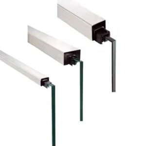
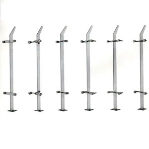
Choosing the Right Post Material and System Strength
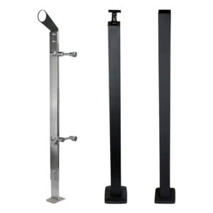
Material Specifications Dictate Longevity
The load requirements demand substantial, durable materials. Low-cost systems utilizing hollow posts, thin-gauge steel, or inferior Grade 304 stainless steel introduce significant long-term risks: corrosion, excessive deflection, and potential load failure. This often creates a “buy it twice” scenario where initial savings are erased by premature replacement and liability concerns. Investment should prioritize specifications proven for durability: solid bar stock posts and Grade 316 stainless steel for superior corrosion resistance, especially in coastal or harsh environments.
The Importance of Proprietary Engineering Data
Beyond generic material advice, the single most important document is the manufacturer’s engineering specification sheet. This proprietary data lists the rated maximum post span and concentrated load capacity for their specific system configuration. This is your only guarantee that the chosen spacing will meet the code-mandated loads. Never proceed without this verification; it bridges the critical gap between safety outcomes and the unregulated methods to achieve them.
Evaluating Post and Material Performance
Selecting components requires a total cost of ownership analysis. The table below compares common material choices and their associated long-term performance risks.
| Material/Feature | Performance Grade | Long-Term Risk |
|---|---|---|
| Hollow posts | Low | Deflection, load failure |
| Thin-gauge steel | Low | Corrosion, premature replacement |
| Grade 304 stainless | Moderate | Corrosion in harsh environments |
| Grade 316 stainless | High | Excellent corrosion resistance |
| Solid bar stock posts | High | Minimal deflection, durable |
Source: Technical documentation and industry specifications.
Practical Installation Tips: On-Center Measurements and Rail Ends
Mastering On-Center Measurement
A common and costly installation error is misunderstanding on-center (OC) measurement. Post spacing is always measured from the center of one post to the center of the next. Your top rail must be ordered to cover this exact OC distance. If installers measure the gap between the inner or outer edges of posts, the rail will be incorrectly sized, causing rework, waste, and project delays. Explicitly clarify and double-check OC measurements during the planning and ordering phase.
Accounting for Rail Ends and Transitions
At rail ends, particularly where the deck meets a house, you must plan for the termination. A typical 1.5 to 2-inch gap is left between the house and the first post. You must ensure this final opening, like all others, complies with the 4-inch sphere rule. These geometric details underscore why complex deck layouts benefit from professional design tools or manufacturer consultation to avoid planning errors that manifest on-site.
When to Use Intermediate Posts for Longer Spans
Defining the Role of Intermediate Posts
Intermediate posts, or “pick” posts, are a strategic tool for managing deflection in longer spans where full structural posts are spaced beyond the ideal 4-6 foot range. Their sole function is to provide mid-span support for the top rail and cables; they do not transfer the primary structural load down to the deck frame. This allows for cleaner sightlines with fewer bulky structural posts while maintaining system integrity and controlling cable sag.
Application in a 30-Foot Run
In a 30-foot run using structural posts at 7.5-foot centers, adding an intermediate post at the midpoint of each span (effectively creating a 3.75-foot support interval) would dramatically increase rigidity. This hybrid approach is often more cost-effective and aesthetically pleasing than adding full structural posts at 4-foot centers. It’s a direct application of the engineering compromise, enabling designers to meet performance requirements through intelligent support strategy.
Calculating Vertical Cable Spacing for Your Railing Height
Applying the Sphere Rule Vertically
Vertical spacing is governed by the same 4-inch sphere rule. The goal is to distribute cables evenly from top to bottom. Using a target installed spacing of 3 inches to account for deflection, apply the formula: Number of Cables = (Railing Height / Cable Spacing) – 1. For a standard 36-inch residential guard: (36 / 3) – 1 = 11 cables. This ensures the bottom cable is positioned correctly off the deck surface and the top cable aligns properly with the top rail attachment.
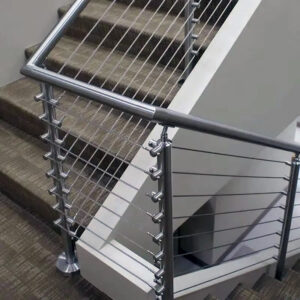
The Staircase Exception
Stair railings operate as a separate subsystem with distinct rules. They are often governed by a 6-inch sphere rule for the triangular opening at the tread and may require a 42-inch minimum height. These exceptions significantly impact design complexity, requiring dedicated layouts and sometimes specialized cable railing fittings and components to navigate angles and meet code.
Vertical Spacing Calculations
The table below provides quick-reference calculations for vertical cable spacing based on common railing heights.
| Railing Height (in) | Cable Spacing Target (in) | Number of Cables |
|---|---|---|
| 36 | 3 | 11 |
| 42 | 3 | 13 |
| Staircase (varies) | ≤ 6 (sphere rule) | Project-specific |
Note: Formula: Number of Cables = (Railing Height / Cable Spacing) – 1.
Source: ICC IRC Section R312 Guards. This code governs maximum opening limitations, which directly dictates the installed vertical cable spacing to prevent a 4-inch sphere from passing through.
Key Questions to Ask Your Supplier and Local Building Department
Verifying System Engineering
Your supplier must provide certified engineering specifications. Ask for the maximum allowable post span and concentrated load capacity for their specific system configuration. Confirm material grades (e.g., 304 vs. 316 stainless), post construction (hollow vs. solid), and whether the warranty covers long-term performance against excessive deflection. This due diligence is your primary defense against under-engineered components.
Navigating Local Code Amendments
Always consult your local building department before finalizing plans. Jurisdictions frequently amend model codes, requiring 42-inch rail heights, specifying cable spacing rules, or even banning certain designs due to the “ladder effect.” This regulatory patchwork makes local approval the final, non-negotiable step. Submit your plan, including post spacing calculations and hardware details, for review to mitigate risk and ensure your 30-foot run is compliant from the outset.
The decision framework for a 30-foot cable railing run prioritizes verified engineering over rules of thumb. First, establish the maximum allowable post span for your specific system, then optimize spacing for performance within that limit. Second, select materials based on total cost of ownership, prioritizing corrosion resistance and solid construction to ensure lasting compliance. Third, validate the entire plan through dual channels: manufacturer specifications for system capability and local building department for jurisdictional approval.
Need professional guidance to engineer a safe, compliant cable railing system for your project? The experts at Esang provide the technical specifications and project support to translate these calculations into a successful installation. For a detailed consultation on your specific deck geometry and local requirements, you can also Contact Us.
Frequently Asked Questions
Q: How do building codes define the safety requirements for cable railing systems?
A: The International Residential Code (IRC) and International Building Code (IBC) establish two primary safety outcomes: the 4-inch sphere rule for openings and specific load capacities. The railing must withstand a 50 lb/ft linear load, a 200 lb concentrated load on the top rail, and a 50 lb load on the cable infill. These codes specify the required performance but not the methods, placing the onus on system design. This means your post spacing and component selection must be engineered to meet these unyielding safety benchmarks, as detailed in IRC Section R312 Guards.
Q: What is the step-by-step process for calculating post spacing on a 30-foot deck?
A: Start by dividing the total run by your system’s maximum allowable span, which is typically 4 to 6 feet for reliable performance. For a 30-foot run with a 6-foot maximum span, you need 5 sections and 6 posts. To reduce deflection, recalculate using a 5-foot span, resulting in 7 posts, or a 4-foot span, requiring 9 posts. This calculation reveals the core trade-off between material cost and system rigidity. For projects prioritizing a sturdy feel and simplified tensioning, you should plan for closer spacing, which increases post count but enhances long-term performance.
Q: Why is the installed cable spacing tighter than the 4-inch code requirement?
A: You must install cables at 3 to 3.25 inches on-center to create a 20-25% buffer against deflection under tension. Cables will sag when pressure is applied, and this pre-emptive reduction ensures the gap never exceeds the 4-inch limit mandated by code. This practice transforms a static minimum into a dynamic performance target for safety. If your installation uses the code maximum as the installed spacing, you risk immediate non-compliance and failure during inspection or under load.
Q: How does post spacing directly affect cable deflection and system safety?
A: Longer spans between posts increase cable sag, which can cause the gap between cables to widen beyond the compliant limit when loaded. Industry-standard spacing of 4-6 feet is engineered to manage this deflection while meeting structural load requirements. Spans exceeding 8 feet often lead to noticeable bowing and safety compromises. This means for longer runs, you should either use closer structural post spacing or supplement wider spans with non-structural intermediate posts for mid-span support, a principle outlined in ASTM F2959.
Q: What are the most critical material specifications for ensuring long-term cable railing performance?
A: Prioritize solid bar stock posts and Grade 316 stainless steel for superior corrosion resistance, especially in harsh environments. Avoid hollow posts and inferior Grade 304 stainless, which risk deflection and premature failure under the code-mandated loads. Always obtain the manufacturer’s certified engineering specs for the rated maximum post span. This means your total cost of ownership analysis should favor these robust specifications over initial price to avoid a costly “buy it twice” scenario and liability concerns.
Q: When should you use intermediate (pick) posts in a cable railing design?
A: Use intermediate posts when the spacing between primary structural posts exceeds the system’s recommended span for controlling cable deflection, typically anything over 4-6 feet. Their role is to provide mid-span support for the top rail and cables without carrying the primary structural load to the deck frame. This allows for cleaner sightlines with fewer bulky posts. For designs aiming for longer spans between structural supports, you should plan for this hybrid strategy to maintain system integrity and meet load requirements.
Q: What key questions should you ask a supplier before purchasing a cable railing system?
A: Require certified engineering specifications detailing the maximum allowable post span and concentrated load capacity for their specific system. Ask for material grades, post construction (solid vs. hollow), and warranty coverage that includes long-term performance against deflection. Simultaneously, always verify requirements with your local building department, as amendments for height or cable spacing are common. This dual verification means you must secure supplier data and local approval before purchase to mitigate compliance risk and ensure a safe installation.