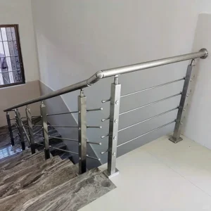
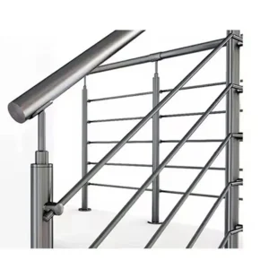
Railing anchorage responsibility is never a single role; it splits into design criteria, project-specific connection engineering, product and drawing data, field-condition reporting, installation execution, and acceptance records, and the contract and jurisdiction decide who holds each one. What changes the allocation on a given job is concrete: whether the guard design is a deferred submittal carrying its own design professional, what the specification says about who sets the load basis, and whether the substrate at each post location was engineered to receive anchor loads. Anchorage here means the whole load path from the post base through the fixing into the supporting structure, which is why it crosses so many parties.
Frame Anchorage as a Shared Project Interface
Anchorage is an interface because the load path starts in one party’s scope and ends in another’s. The guard load arrives at the top of the post, travels down the post as a bending moment, and is resolved at the base as tension, shear and bearing in the supporting slab, beam, curb or wall. The railing supplier controls the geometry and material above the base plate; whoever designed the supporting structure controls what that structure can accept.
Treating it as a shared interface changes what you ask for. Instead of asking whether the railing is “strong enough”, you ask which party set the load basis, which party resolved the anchor into the actual substrate, and which party confirmed the substrate at each location matches that assumption. Those are three different answers on most projects, and they can belong to three different people.
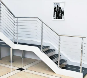
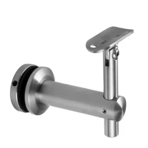
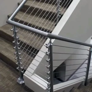
The interface also moves with mounting type. A post-mounted guard concentrates the entire guard load into a small base footprint, so edge distance, slab thickness, reinforcement position and any topping or waterproofing layer all become part of the anchorage question. A wall-mounted rail shifts the same question to the wall: its construction, the presence of blocking or structural backing, and whether the fixing can reach it. Fascia and side-mounted posts add a third variation, where the load arrives as a couple into a vertical face rather than a horizontal one. The parties involved differ in each case, which is why a generic statement of responsibility rarely survives contact with the drawings.
Separate Design Criteria, Connection Engineering, and Product Data
| Workstream | Project inputs | Decision or deliverable | Responsibility boundary |
|---|---|---|---|
| Design criteria | Project loads, building scope, contract terms, and applicable jurisdiction | Criteria the railing and anchorage design must satisfy | The contract and jurisdiction determine the named design and approval parties; a component submittal alone does not assign those roles. |
| Connection engineering | Design criteria, substrate condition, anchor selection, base geometry, access, and envelope interfaces | Project-specific anchorage and connection decisions | The responsible project party must resolve the connection for the actual project conditions before fabrication. |
| Product and drawing data | Post, base, hardware, anchoring-system, and drawing information | Component compatibility inputs for coordination | Product data supports coordination but does not by itself establish field-specific design or code approval. |
Keeping design criteria, connection engineering, and product data apart is the single most useful discipline in managing railing anchorage responsibility, because each one answers a different question and none of them can be substituted for another. Design criteria state what the railing and its anchorage must resist and comply with. Connection engineering resolves those criteria into a specific anchor, embedment and base arrangement for the conditions at hand. Product and drawing data describe what the components are and how they fit together.
ASTM E985-24, which covers permanent metal railing systems and rails for buildings and excludes ballasted systems and certain specified adult-workplace systems, is explicit in its public scope that field-specific design criteria sit with the designer, the specification writer, and code agencies. Its general building-railing criteria do not resolve the anchorage conditions on an actual project. That is a helpful boundary to hold in a meeting: a standard can tell you what class of criteria must exist, but someone named on your project still has to produce them for your slab, your edge distance and your post spacing.
Connection engineering is where the most expensive mistakes hide, because it depends on facts that only become firm late. The substrate condition, the anchor type, the base plate geometry, the clearance available to drill and tighten, and any interface with waterproofing or cladding all feed a single decision. If that decision is still open when fabrication starts, the base plates may be drilled to a bolt pattern the structure cannot accept, and the correction happens on site with the worst available tools.
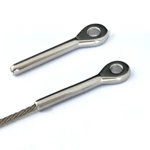
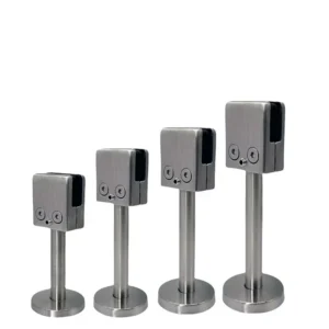
Product and drawing data is genuinely useful for coordination and genuinely limited as evidence. An ESANG submittal for posts, base covers, mounting hardware and anchoring components tells you bolt hole pattern, base footprint, material grade, finish and fastener compatibility, which lets a connection engineer work with real dimensions rather than placeholders. It does not, by itself, assign the engineer-of-record role or constitute code approval. Those roles come from the contract and the authority having jurisdiction, and a supplier cannot assume them by issuing a drawing.
Define Supplier Drawing and Component-Compatibility Inputs
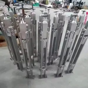
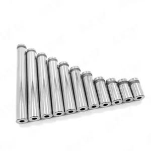
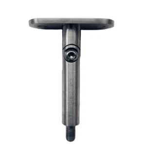
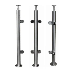
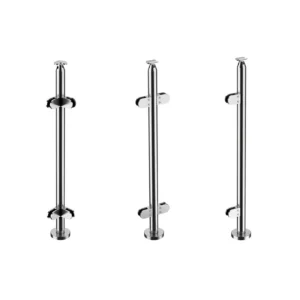
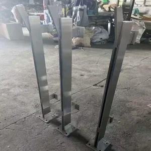
The supplier’s contribution to anchorage is a defined set of dimensional and material facts that let someone else complete the connection decision. For post-mounted systems, that means base plate outline and thickness, bolt hole positions and diameters, the post section and wall thickness, the weld or mechanical connection between post and base, the stainless grade, and the finish. For anchoring hardware supplied with the system, it means the fastener type, size, thread and material, plus whatever fitting clearance the base cover or trim requires.
Component compatibility is a real engineering question and worth separating from load capacity. Mixing stainless grades and fastener materials at the base, or bringing a stainless base plate into direct contact with a dissimilar metal in a wet or coastal location, creates a galvanic couple that attacks the less noble material. Coastal and pool environments also drive the grade decision for the post, the fixing and any embedded component, because chloride exposure attacks the passive layer on austenitic stainless and crevices under base plates and washers concentrate that attack. Those are compatibility and durability facts the supplier can state; the specified grade and finish for the project still come from the specification.
Geometry compatibility deserves the same attention. A base plate footprint that looks generous on a drawing may put anchors inside the edge distance the structural design requires, or land them over a post-tensioning tendon or a reinforcing bar. Drilling clearance is another practical constraint: a slim base cover or a post set close to a parapet may leave no room for a drill body and chuck at the required angle. These are dimensional facts the supplier can confirm from shop drawings, and the earlier they are compared against the structural drawings, the fewer field improvisations follow.
When you prepare a shop drawing review, the productive question is not whether the drawing looks correct but whether each dimension it carries has a corresponding confirmation on the structural side: anchor positions against edge distances and reinforcement, base height against finished floor and waterproofing build-up, and post spacing against the spacing the load basis assumed.
Record Installer Findings and Field-Change Escalation
The installer’s role in anchorage responsibility is to record what is actually there and to route any departure back to the party who owns the decision, with evidence tied to a specific location. A finding without a location is almost useless; a finding with a grid reference, a post number, a photograph and a measurement can be evaluated by the responsible party without a second site visit.
What is worth recording is the set of facts the connection decision assumed. Slab or wall thickness where it can be observed or probed, any hollow, topping layer or screed between the surface and the structural element, concrete condition at the drilled location, measured edge distance from the actual post position to the actual slab edge, obstructions found during drilling, and discrepancies between the laid-out post positions and the drawn positions. Where a core or probe reveals something unexpected, that observation belongs in the record even if the installation continues elsewhere.
Escalation works best as a short, unambiguous sequence rather than a conversation. The installer stops work at the affected locations, records the condition with location-specific evidence, and passes it to the project party named for connection decisions. Proposed alternatives from the field, such as a different anchor type, relocated holes, a larger base plate or an added backing element, are proposals until the responsible party accepts them. Whether work at that location resumes is decided under the project’s approved procedure by its designated approver, not by the installer or the supplier.
A practical habit that saves time: record the conforming locations too, not only the problem ones. When a departure is later reviewed, the reviewer needs to know whether the condition is isolated or systematic, and only a complete location record answers that.
Align Submittal, Inspection, and Handover Evidence
| Evidence stage | Record to align | Décision approuvée | Limit of the record alone |
|---|---|---|---|
| Submittal | Supplier drawings and component data for posts, bases, hardware, and anchoring systems | Compatibility and coordination before fabrication | It does not assign the engineer-of-record or code-approval role. |
| Field inspection | Location-specific findings for the substrate, anchors, welds, base plates, and site tolerances | Whether actual conditions match the basis used for installation and whether a departure must be escalated | It does not replace the project-specific design criteria or connection decision. |
| Handover and acceptance | Acceptance records linked to the installed condition and resolved field departures | Whether the required project evidence is assembled for closeout | The contract and jurisdiction still govern who reviews and accepts the records. |
The three evidence stages are only useful when the same anchorage facts can be followed from one to the next, which means the identifiers must match. Post numbers and grid references used in the shop drawings should be the ones used in the field records and in the acceptance documents, so that a question about one base plate can be traced in both directions without reconstruction.
Contract review duties sit inside this chain, and the AIA Contract Documents explanation of A201-2017 Section 3.12.6 is a clear illustration of the distinction: under that named U.S. contract form, a contractor’s review of a subcontractor’s submittal addresses materials, field measurements, field construction criteria, and coordination with the work and the contract documents, rather than simply forwarding supplier data onward. That distinction matters for anchorage because field measurements and field construction criteria are exactly where supplier data stops and project conditions begin. The responsibilities actually established on your project are whatever your own contract sets out, so apply the principle rather than the specific form.
Deferred submittals change the sequence rather than the responsibility split. Portland Permitting and Development’s deferred submittal guidance lists manufactured guardrails as a deferred-submittal example and separates three distinct functions: the professional responsible for the deferred design, the main-permit designer’s review for conformance with the permitted design, and the building official’s approval. Under that local procedure, design or layout changes require a permit revision, and special inspections within scope must appear on the drawings. That allocation is Portland, Oregon procedure and does not generalize worldwide, but the structure it makes visible is worth borrowing: a review stamp and a design seal serve different stated functions, and neither one converts supplier component data into connection engineering, code approval or a completed inspection.
The reason to align these records before closeout rather than during it is that anchorage evidence degrades quickly. Once base covers are fitted, finishes are applied and access equipment is removed, the condition at each base plate can no longer be observed. Photographs taken at the time of drilling and fixing, keyed to post numbers, are the only practical way to answer later questions about what the anchor went into.
Close Each Open Decision Under the Project’s Responsibility Matrix
| Open decision | Question to close | Handoff controlled |
|---|---|---|
| Project loads | What project-specific load basis governs the anchorage? | Design criteria into connection engineering |
| État du substrat | What substrate condition is assumed, and what condition is found at the installation location? | Field findings into the project-specific connection decision |
| Anchor selection | Which anchoring approach is selected for the criteria, substrate, and component data? | Connection engineering into fabrication and installation |
| Base geometry | How does the post base geometry coordinate with the planned connection? | Supplier drawing and component data into connection engineering |
| Access | Can the planned connection be installed at the intended location with the available access? | Project coordination into fabrication and installation planning |
| Envelope interfaces | How will the anchorage coordinate with the project-specific envelope interface? | Interface coordination into the final connection decision |
Every open anchorage item should carry a named owner and a date by which it is decided, and the project’s responsibility matrix is where that assignment lives. Six items recur: the project load basis, the substrate condition at each location, the anchor selection, the post base geometry, the physical access to install the connection, and the interface with the building envelope. Each one, left open, blocks a specific downstream step rather than the project as a whole, which is why tracking them individually is more effective than tracking “anchorage” as one line.
Order matters among them. The load basis has to be settled before anchor selection means anything, because the anchor is sized to a force. Substrate condition and base geometry both feed the same connection decision, so either one can hold it up. Access and envelope interfaces are often discovered last and are the items most likely to force a change after fabrication, so they repay being raised early: a post base that must sit on a waterproofed terrace, or one that lands behind a cladding return, changes the connection before it changes the schedule.
Set a hard cutoff at fabrication release. Base plate thickness, bolt hole pattern, post section and base height become fixed metal at that point, and reopening any of them afterward means modifying parts on site, with the finish and corrosion performance that site modification implies on a stainless system in an exposed or coastal location.
For the supplier conversation that supports these closures, have the structural drawings covering the post locations, the specified stainless grade and finish, the governing load criteria as stated in the specification, the post layout with spacing and edge distances, the substrate build-up at the mounting surface including any topping or waterproofing, the exposure category, and the project’s responsibility matrix showing who owns the connection decision. With those in hand, the component data can be matched to real conditions, and the remaining open items can be closed by the parties who actually hold them.
Questions fréquemment posées
Q : Who should own each railing anchorage decision?
A : Assign ownership through the project-specific responsibility matrix, using the contract and applicable jurisdiction to name the parties. Give each open input and deliverable—such as the load basis, substrate findings, connection decision, component data, installation work, and acceptance record—one identified owner and decision point before fabrication.
Q : When is a railing post anchorage package ready to release for fabrication?
A : Release it only after the project team has closed the decisions that affect the actual connection. Check that the governing loads, assumed and observed substrate condition, anchor selection, base geometry, installation access, and envelope interfaces have been resolved by the responsible parties rather than left as unassigned coordination notes.
Q : Can an ESANG component submittal serve as the project-specific anchorage design or code approval?
A : No. Supplier drawings and data can support component compatibility and coordination, but the contract and jurisdiction determine who owns connection engineering, field-specific design, review, and approval. Use the submittal as an input to those decisions, not as evidence that those roles have been completed.
Q : What should happen when site conditions differ from the anchorage basis used before fabrication?
A : Record the departure at the specific installation location and route it to the party responsible for the affected decision before treating the planned connection as applicable. The record should identify the observed condition, the assumption or detail it conflicts with, and the related substrate, anchor, base, access, tolerance, or envelope issue that needs resolution.
Q : How can the project team check whether its anchorage closeout record is complete?
A : Trace each installed location from its approved project criteria and connection decision through the coordinated component data, field findings, resolved departures, and final acceptance record. Then confirm that the review and acceptance parties named by the contract and jurisdiction have the evidence required for their roles.