Permit sets that arrive at the engineer’s desk with hardware selected from catalog images — but no confirmed load path — tend to produce the same outcome: a redesign cycle that compresses fabrication schedules and pushes procurement back by weeks. The failure is not usually a bad product choice; it is a sequencing problem where mounting method, glass build-up, and substrate condition are treated as separate decisions owned by separate parties, when structurally they are one decision that must be resolved before any product is named. A mismatched anchor condition discovered at engineer review can invalidate the entire guard package even if the hardware itself is code-compliant. Working through this guide will sharpen your ability to identify which specification fields must be locked before RFQ and where the handoffs between architect, glass fabricator, and hardware supplier are most likely to produce gaps.
What the hardware specification must decide before product selection
The specification work that prevents redesign happens before any catalog is opened. Five code-level questions must be answered first, and the answers drive every downstream product decision.
Guard height is not a preference — it is a threshold with direct legal consequence. Under the 2021 International Building Code, commercial occupancies require a 42-inch guard; residential construction under the IRC requires 36 inches. Specifying the wrong height for the occupancy type does not produce a marginal non-conformance; it requires physical rework of every post and glass panel in the affected zone after the permit is rejected. The trigger for whether a guard is required at all depends on geometry: a guardrail is required where a walking surface edge has a drop greater than 30 inches measured within 36 inches horizontally. Mapping that condition across every railing zone at the start of the project determines scope; missing an elevated zone that technically triggers the requirement is a common inspection failure.
Load requirements under IBC Chapter 10 are not advisory. The top rail must resist a 200-pound concentrated load and a 50-pounds-per-linear-foot horizontal load simultaneously; the infill must resist a 50-pound load applied over a one-square-foot area. These figures are the structural baseline that any engineer reviewing the guard package will check against, and they must be met by the combination of hardware, glass, and substrate — not by the hardware alone. Glass safety glazing requirements follow the same logic: laminated safety glass must comply with either CPSC 16 CFR 1201 Category II or ANSI Z97.1 Class A. Substituting non-safety glass is one of the most common code violations flagged during permit review, and it results in full glass replacement cost.
The top rail question deserves its own decision before any hardware is specified. For most guard systems, a top rail is structurally required. Omitting it is permissible only when the glass panels have been tested and pass ASTM E2353 as a self-supporting system — a third-party test validation, not a designer’s judgment call. Where that test evidence exists, eliminating the top rail reduces visual obstruction and simplifies the hardware package. Where it does not, specifying a frameless look without a rail creates a compliance gap that surfaces at inspection.
| نقطة تفتيش | Requirement (Code Threshold) | ما أهمية ذلك |
|---|---|---|
| Guard height | 36 in. residential (IRC); 42 in. commercial (IBC) | Wrong height triggers redesign and code rejection |
| Guardrail trigger | Required where drop >30 in. within 36 in. horizontally from edge | Determines if a railing system must be installed at all |
| Top rail and infill loads | Top rail: 200 lb concentrated / 50 plf; Infill: 50 lb over 1 ft² | Core structural loading criteria for permit approval |
| Glass safety standard | Laminated safety glass to CPSC 16 CFR 1201 Cat II or ANSI Z97.1 Class A | Non‑safety glass is a frequent code violation that halts approval |
| Top rail omission | Only allowed if glass passes ASTM E2353 (self‑supporting) | Eliminates top handrail cost and visual obstruction when justified |
Every row in that table represents a decision that, if deferred, becomes a constraint imposed on procurement rather than a choice made by the specifier.
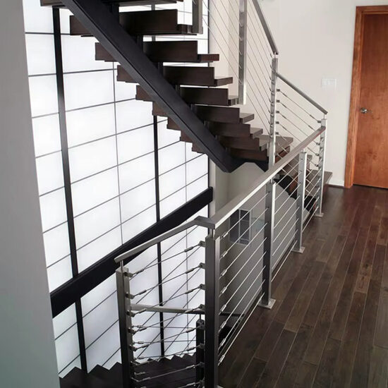
Mounting method, glass build-up and substrate as one load path
The most consistent source of engineer-review redesign is treating mounting method, glass thickness, and substrate condition as three sequential line items rather than a single structural decision. These three variables define the load path — how force moves from the glass panel through the hardware into the building structure — and a mismatch at any point in that path can invalidate the others even when each component is individually code-compliant.
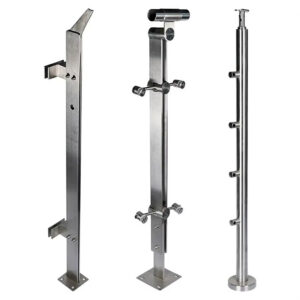
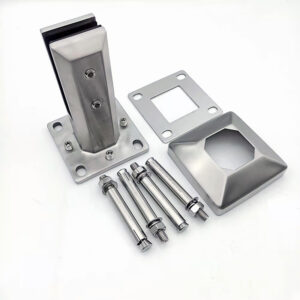
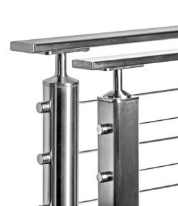
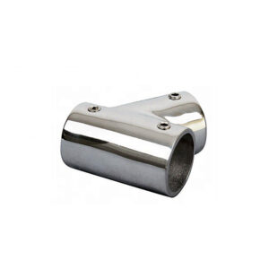
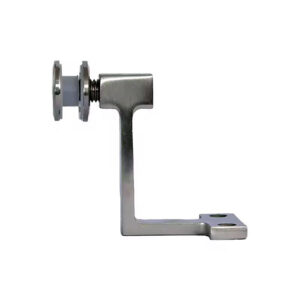
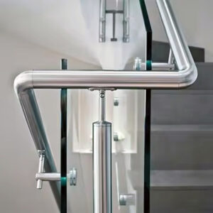
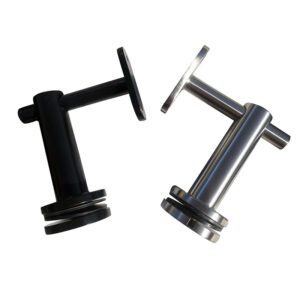
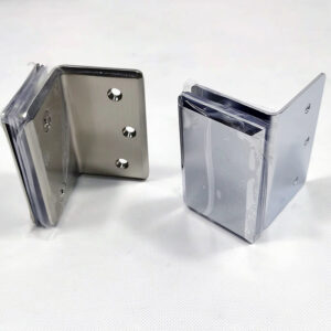
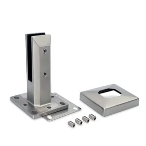
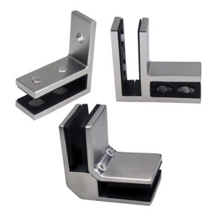
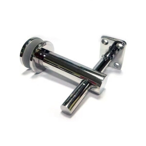
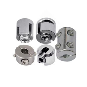
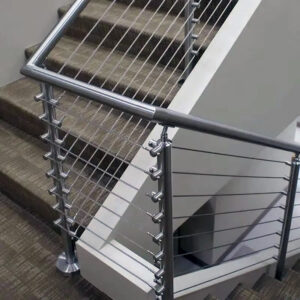
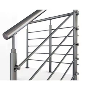
Base shoe systems and standoff systems (clamps and spigots) create fundamentally different load profiles. A base shoe channel distributes the glass panel’s lateral load continuously along the channel length and into the substrate below it, which reduces peak stress at any single anchor point. A standoff system — whether surface-mount spigots or point-fixed clamps — concentrates the same load at discrete fastener locations. Neither approach is structurally superior in the abstract; the right choice depends on what the substrate can accept. A concrete slab with adequate embedment depth handles concentrated spigot loads well. A wood-framed deck with variable joist spacing may distribute load more reliably through a continuous base shoe. The decision must be made after the substrate condition is verified, not before. حنفية زجاجية مثبتة على السطح و round glass clamps are appropriate for the right substrate conditions, but their load concentration demands that anchor locations be individually confirmed — a step that is often assumed to be someone else’s responsibility.
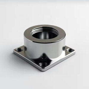
Substrate mounting position adds a second layer to that decision. Fascia mounting — fixing hardware to the side face of a beam or rim joist — typically provides a stiffer, stronger connection point than deck-surface mounting because the beam face resists horizontal load more directly than the deck surface above it. Deck mounting on wood-framed construction often requires through-bolts rather than lag screws to achieve the required pull-out capacity under horizontal loading; lag screws into the top face of framing may be adequate for some substrate conditions but should not be assumed without verification. Using undersized fasteners without that check is a documented failure mechanism, not a theoretical concern.
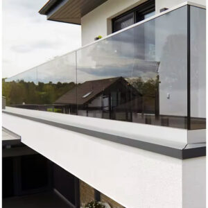
Glazing method closes the third variable in the load path. Dry glaze systems seat the glass panel in a gasket or setting block without sealant, which allows faster installation and easier future panel removal. Wet glaze systems use sealant at the glass-to-hardware interface, which improves weather resistance and long-term performance in exposed exterior conditions. For a covered interior atrium application, the installation speed and adjustability of dry glaze may be the better outcome. For a coastal balcony with sustained wind-driven rain exposure, wet glaze’s weather-sealing performance justifies the additional installation coordination. The choice affects both long-term durability and the sequence in which glazing work must be coordinated with the hardware installation team.
| Load Path Decision | Options | Trade‑Off / Coordination Point |
|---|---|---|
| طريقة التركيب | Base shoe vs Standoff (clamp/spigot) | Continuous load vs concentrated load; base shoe uses anodized aluminum with drainage, standoff uses 316SS with two‑way alignment |
| Glazing method | Dry glaze vs Wet glaze | Faster installation and easier adjustments vs better long‑term weather resistance for exterior |
| Substrate mounting | Deck (top) vs Fascia (side beam) | Fascia typically stiffer and stronger; deck mounting may require through‑bolts instead of lag screws |
The handoff between architect, glass fabricator, and hardware supplier is where hole positions and anchorage evidence most often fall through — each party may reasonably assume the other party owns that coordination, and the gap surfaces at fabrication or inspection rather than at the specification stage where it is cheap to resolve.
Stainless grade and finish choices by exposure zone
Material grade selection for glass railing hardware is often treated as a finish decision — a choice between visual options on a finish schedule — when it is actually a corrosion-zone decision with direct consequences for service life and maintenance cost. The specification should start with the exposure zone, then derive the required material grade.
For most interior applications and low-humidity exterior environments well away from the coast, 304 stainless steel provides adequate corrosion resistance with good formability and a wide range of available finishes. Moving to exterior applications with moderate exposure — elevated humidity, occasional salt air, urban pollution — shifts the appropriate baseline to 316 stainless, which contains molybdenum and resists chloride-induced pitting more reliably than 304 in those conditions. Neither grade is non-compliant in appropriate environments; the risk with 304 in a 316-appropriate zone is not immediate failure but accelerated surface corrosion that generates maintenance obligations and eventual structural concern if pit corrosion reaches load-bearing cross-sections.
Within roughly five miles of a coastline — or in zones with heavy acid rain, industrial fallout, or sustained high UV — the corrosion demand exceeds what 316 stainless reliably manages over a project’s expected service life. Industry corrosion-zone practice points toward 2205 duplex stainless steel or anodized aluminum with a fluoropolymer finish as the specified response to those aggressive conditions. The 2205 duplex alloy provides roughly twice the yield strength of 316 alongside superior chloride resistance, which makes it appropriate for both structural hardware and decorative components in coastal environments. Fluoropolymer-finish aluminum addresses the same corrosion performance goal with different structural properties; it is commonly specified for base shoe channels where the continuous aluminum extrusion benefits from factory-applied coating durability rather than relying on field-applied treatments.
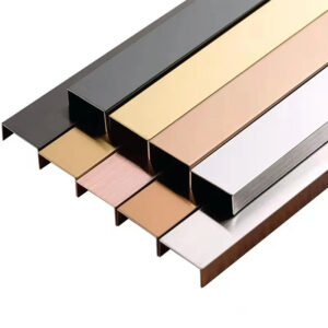
Finish selection within the appropriate grade carries its own downstream consequence. Brushed or satin finishes hide minor surface abrasion and fingerprinting in high-traffic applications, but the directionality of the brushed pattern must be specified and coordinated with fabrication — random vs. unidirectional brushing on the same project produces a visible inconsistency at connections and corner details that is difficult to correct in the field. Mirror-polished finishes maximize light reflection and suit premium commercial interiors but require more demanding maintenance protocols and show surface damage from contact with tools or hardware during installation. Specifying the finish without specifying the maintenance expectation sets up a dispute between installer and owner at project handover.
For a broader view of how grade and finish decisions interact with system selection across project types, the Complete Stainless Steel Glass Railing Guide provides additional context on material selection across residential and commercial applications.
Approval documents that separate comparable supplier quotes
An ICC-ES evaluation report looks like a permitting shortcut, and for many standard installations it functions as one — but it creates a hidden review obligation that, when missed, produces permit denials on projects where everything else is correct. The report establishes a pre-tested compliance baseline covering glass type, top rail requirements, panel sizes, wind loads, and anchor details. The condition is that every project-specific parameter must match the report’s scope line by line. A glass thickness, panel dimension, or anchor configuration that falls outside the report’s tested range is not covered by it, and the permit application reverts to requiring engineer-stamped calculations for the non-conforming elements.
This review obligation is more demanding than it appears on a bid comparison. A supplier quoting on the basis of an ICC-ES report may be offering genuine compliance coverage for a standard configuration and incomplete coverage for the actual installed conditions — and both quotes look the same on a fee schedule. The document check that separates those two outcomes is a side-by-side comparison of actual site conditions against the report’s specific coverage: glass species, interlayer type if laminated, panel size limits, wind load values, substrate type, and anchor spacing. Any line that does not match requires an engineer-designed alternative for that condition, which adds both cost and schedule.
Jurisdictional supplements create a second layer that the ICC-ES report may not address at all. Florida’s High Velocity Hurricane Zone carries wind load and impact-resistance requirements that standard evaluation reports were not written to cover. Specifying a system on the basis of an ESR number without confirming local authority acceptance of that report for the specific project location can produce a permit denial even when the report itself is valid and current. Florida HVHZ is a well-documented example, but the principle applies wherever local amendments extend beyond the model code that the ICC-ES report references. Confirming local authority requirements before selecting a supplier document package is a process step, not an optional risk management choice.
The practical implication for bid comparison is that a complete supplier submittal package must contain more than a product catalog and a price. System drawings in both PDF and DWG format, installation instructions with anchor details, specification sheets, a limited warranty, and the applicable evaluation report together constitute a document package that supports both permit submission and apples-to-apples quote comparison. A supplier who provides only the evaluation report number without the supporting drawings and installation instructions is leaving the specifier to reconstruct the permit submission from incomplete inputs — a coordination burden that transfers to the architect or contractor and inflates project management cost beyond what the hardware savings justify.
| Required Document / Evidence | What It Must Cover | Risk If Omitted or Unclear |
|---|---|---|
| ICC‑ES evaluation report (e.g., ESR‑4799) | Glass type, top rail requirement, panel sizes, wind loads, anchor details | Permit application may be rejected without a pre‑approved compliance baseline |
| Project‑specific line‑by‑line match | All site conditions match the ICC‑ES report; any deviation requires an engineer‑designed alternative | Using a report that does not cover the as‑built configuration leads to non‑compliance |
| Jurisdiction supplements (e.g., Florida HVHZ) | Confirm with local authority whether supplemental requirements exist beyond the standard report | Permit denial if local amendments are not addressed |
| Supplier submittal package | System drawings (PDF/DWG), installation instructions, specification sheets, limited warranty, quote forms | Quotes cannot be compared apples‑to‑apples and permit submission remains incomplete |
| Structural calculations (when required) | Stamped by licensed engineer for complex or non‑standard installations | Permit application rejected if structural justification is absent |
For a detailed review of how these documents interact with IBC, IRC, and ANSI Z97.1 requirements at the permit submission stage, the Stainless Steel Glass Railing Building Code Compliance guide addresses the full regulatory framework in detail.
Final specification fields to lock before RFQ
A specification that reaches RFQ with open fields does not produce a clean bid. It produces a clarification cycle where each supplier fills the gaps with their own assumptions — different glass thicknesses, different interlayer materials, different drainage approaches — and the quotes that come back cannot be compared on merit. Locking every specification field before issuing the RFQ is not administrative overhead; it is the control mechanism that keeps procurement scope stable and prevents substitution risk from compressing the installation schedule.
Glass thickness is the field most likely to be left open with the expectation that suppliers will recommend. The appropriate value is not a product preference — it follows from the mounting method. Captured or framed systems using a base shoe channel work with 3/8-inch glass because the continuous channel supports the panel perimeter. Structural or frameless systems that rely on clamps or spigots for point support require 1/2-inch minimum thickness to carry the concentrated loads at those discrete points. For standard residential exterior applications, 1/2-inch tempered glass is the baseline. Commercial applications and projects in high-wind zones typically require 9/16-inch laminated glass to meet both structural and safety glazing requirements. Under CPSC 16 CFR 1201, the safety glazing compliance requirement applies regardless of thickness — the glazing standard is a floor, not a consequence of thickness selection.
Interlayer specification for laminated glass is a failure risk that often escapes attention because it appears to be a manufacturing detail rather than a performance decision. PVB interlayer performs well in interior applications where UV and moisture exposure are controlled. In exterior applications — particularly coastal and high-humidity zones — PVB is vulnerable to edge delamination and UV-driven yellowing over time. SGP (SentryGlas Plus) interlayer provides significantly higher moisture resistance, greater stiffness, and better UV stability, and is the appropriate specification for exterior laminated glass under ASTM C1172-24e1 standards. Specifying laminated glass without specifying the interlayer type leaves room for a supplier to substitute PVB in a location where SGP performance is required, which may not be visible at installation but will manifest in adhesion degradation or discoloration within the warranty period.
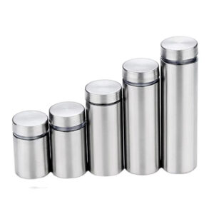
Drainage configuration is similarly underspecified in exterior zones. قنوات الأحذية ذات القاعدة الزجاجية designed with built-in drainage are available, but the specification must confirm whether a gap is maintained below the glass panel for water evacuation, and whether the base rail design is appropriate for the debris load of the specific installation location. Fully enclosed base-rail channels in tree-canopy environments or locations prone to leaf debris collect organic material that holds moisture against both the glass edge and the aluminum extrusion, accelerating corrosion at the glass-to-channel interface. The specification field for drainage is not a preference; it is a maintenance and corrosion consequence that compounds over the system’s service life.
Sphere clearance limits apply to the infill and stair geometry independently, and both must be confirmed before fabrication drawings are issued. Standard guard infill must block a 4-inch sphere. Stair guard infill uses a different limit — 4-3/8 inches — because stair geometry is addressed separately in code. The triangular opening formed by a stair railing, stair tread, and stair riser must block a 6-inch sphere. These are not interchangeable; applying the 4-inch sphere rule to a stair triangle opening does not satisfy the 6-inch requirement, and the error is routinely caught at inspection after fabrication is complete. The maximum straight section length limit of 6 feet applies to structural integrity under load and must be coordinated with glass panel layout before shop drawings are generated.
| Field to Lock | Approved Value / Criteria | Why Deviation Must Be Caught |
|---|---|---|
| Maximum straight section length | 6 ft | Exceeding risks structural sag or failure under load |
| Glass panel thickness | 3/8 in. for captured (framed) systems; 1/2 in. for structural (frameless) systems | Thickness must match the mounting method to meet load requirements |
| Glass type by application | 1/2 in. tempered for standard residential exterior; 9/16 in. laminated for extreme wind or commercial | Incorrect glass type compromises safety and code compliance |
| Interlayer | PVB for interior; SGP (SentryGlas Plus) for exterior UV/moisture resistance | Wrong interlayer can delaminate or yellow, reducing safety and aesthetics |
| Hardware material by system | Base shoe systems – anodized aluminum; Standoff systems – 316 stainless | Material grade must be specified to match system type and exposure |
| الصرف | Gap under glass panels where drainage needed; avoid fully enclosed base‑rail channels in debris‑prone areas | Poor drainage leads to water collection, corrosion, and debris buildup |
| Infill opening limits | 4 in. sphere for guards; 4‑3/8 in. sphere for stair guards; 6 in. sphere for stair triangle | Prevents child entrapment and is a common inspection check |
Every field in that table represents a procurement variable that, if left open, will be resolved by someone other than the specifier — and resolved in favor of the supplier’s standard product, not the project’s structural or code requirements.
The practical test for a complete glass railing hardware specification is whether every zone has a named mounting method, confirmed substrate condition, locked glass thickness and interlayer type, assigned stainless grade matched to the exposure zone, specified finish with maintenance expectations, and a named approval document whose scope has been checked against actual project conditions. A specification that satisfies all of those fields for every zone is ready for RFQ. One that leaves any of them open is generating future clarification work — the only question is whether that work happens at specification, where it costs time, or at fabrication and inspection, where it costs money and schedule.
Before issuing the RFQ, confirm that the supplier submittal package includes system drawings in both PDF and DWG format, installation instructions with anchor details, the applicable ICC-ES evaluation report with project conditions verified line by line, and any jurisdiction-specific supplements confirmed with the local authority. Those documents are what allow quotes to be compared on actual compliance scope rather than on catalog presentation — and that comparison is the decision the specification is designed to support.
الأسئلة الشائعة
Q: What happens if the substrate condition can’t be verified until after the RFQ is issued?
A: Delay issuing the RFQ until at least a preliminary substrate assessment is complete — even a basic structural review of framing type, joist spacing, and embedment depth is enough to determine whether a continuous base shoe or discrete spigot system is viable. Issuing RFQ without that information means suppliers will quote against incompatible assumptions, and the substitution risk lands on procurement when the engineer reviews the guard package. If site access genuinely prevents early verification, scope the RFQ to both mounting methods with pricing contingent on substrate confirmation, and lock the final selection before shop drawings are released.
Q: If a project spans multiple exposure zones — say, an interior atrium connected to an exterior coastal balcony — does the entire system need to be specified to the higher corrosion standard?
A: No, but each zone must be specified independently with its own material grade assignment. Interior atrium hardware can be specified to 304 stainless while the exterior coastal zone is specified to 2205 duplex or fluoropolymer-finish aluminum — provided the specification clearly defines the zone boundary and the fabricator is given separate material callouts for each zone. The risk is at the transition detail: hardware that bridges both zones must default to the higher grade, and that junction point should be explicitly called out in the drawings rather than left to fabricator interpretation.
Q: At what point should the glass fabricator be brought into the specification process relative to the hardware supplier?
A: Both parties should be engaged before hole positions and panel dimensions are finalized, not sequentially. The friction point the article identifies — where each party assumes the other owns anchorage evidence or hole positions — is most reliably closed by a coordinated submittal review that includes hardware anchor layout, glass panel size limits from the ICC-ES report, and fabrication tolerances from the glass supplier in the same session. Bringing the glass fabricator in after the hardware specification is locked often produces a hole-position conflict that requires either re-drilling (if substrate permits) or a complete panel remake.
Q: Is engineer-stamped structural calculations always required, or only when an ICC-ES report doesn’t cover the project conditions?
A: Stamped calculations are required when any project condition falls outside the tested scope of the applicable ICC-ES report — mismatched glass thickness, panel dimensions beyond the report’s limits, non-standard anchor spacing, or substrate types not covered. For fully conforming standard installations where every project parameter matches the report line by line, the evaluation report substitutes for project-specific calculations in most jurisdictions. The exception is where local amendments or supplemental requirements (such as Florida HVHZ wind and impact standards) exceed the model code the report was written against — in those cases, stamped calculations are required for the non-conforming elements regardless of whether an ICC-ES report exists.
Q: When comparing two supplier quotes that both reference an ICC-ES report, what is the most meaningful technical differentiator beyond the hardware price?
A: The coverage boundary of each report against actual project conditions is the differentiator that most often separates genuine compliance from apparent compliance. Two suppliers can both cite valid, current evaluation reports while one report covers the specified glass thickness, panel size, and wind load and the other covers only a subset of those conditions — leaving the balance to require engineer-designed alternatives that add cost and schedule after award. The comparison that resolves this is a line-by-line check of each report’s scope against every project-specific parameter: glass species and interlayer, panel dimensions, wind load values, substrate type, and anchor spacing. The supplier whose report covers the most project conditions without deviation reduces total procurement risk more than a lower unit price that triggers an engineering supplement.