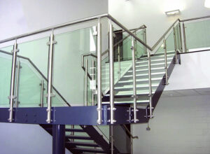
A cap rail that appears in drawings as a trim detail but functions as a structural guard element is one of the most reliably underspecified components in glass railing systems. The ambiguity rarely surfaces during design review — it surfaces at site acceptance, when a polished stainless miter shows a visible gap, a corner return mismatches the post condition, or an inspector asks how the system maintains barrier continuity after a panel failure. Resolving those problems after the glass is already installed is expensive, and off-the-shelf profiles cannot substitute for fabrication details that were never written into the contract documents. The decision that prevents most of this downstream friction is straightforward: declare the cap rail’s function — structural or protective-only — before any other specification detail is written, and let that declaration drive every subsequent fabrication and joinery requirement.
Cap rail function must be stated in the specification
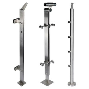
The first specification entry for a glass railing cap rail should not be a profile dimension or a surface finish. It should be a functional designation: is this cap rail part of the guard system’s structural load path, or is it protective edge treatment only? That single declaration determines whether the project requires splice continuity details, corner load transfer, and panel-failure bridging — or only cosmetic joinery. Leaving it unstated does not eliminate those requirements; it only defers the question to a stage where answering it costs significantly more.
The IBC distinguishes guards from handrails, and that distinction matters here. A top rail on glass baluster panels is generally required unless the glass is laminated and has been tested per ASTM E2353 to remain in place after breakage. That exception is narrow and test-dependent; specifying a cap rail as “decorative” does not invoke it. If the laminated glass testing has not been conducted and documented for the specific assembly, the top rail is required, and its structural adequacy must be addressed in the specification.
The practical consequence of omitting the functional designation is not a missed note in the drawings — it is a cascade. Without a structural designation, fabricators have no basis to detail splice plates, welding continuity, or post-connection load transfer. Without a protective-only designation confirmed against code thresholds, the system may still be expected to perform structurally without the detailing to support it. Either way, the ambiguity produces a system that cannot be defended at inspection or accepted without revision.
Profile, joint and corner details for continuous rail
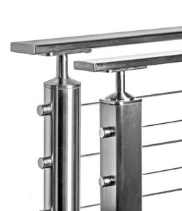
Profile selection for a continuous cap rail carries a compliance boundary that is easy to underestimate when the focus is on visual continuity. A round cap rail profile that falls within graspable handrail dimensions satisfies IBC requirements where hand contact is mandated — on stairways, at required handrail locations, or wherever the system is specified to serve a dual guard-and-handrail function. A square or rectangular profile does not meet graspability requirements under IBC regardless of how the cap rail is otherwise detailed. That is not a preference or an aesthetic judgment. Specifying a square profile for a location that requires a graspable handrail creates a compliance gap that cannot be corrected by adjusting finish or joint method.
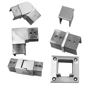
Beyond profile selection, joint and corner treatments are the most common source of site acceptance delays on continuous cap rail runs. Corners require a decision between field-mitered cuts and shop-fabricated corner pieces, and that decision belongs in the specification, not in the installer’s hands on site. Unspecified corners produce inconsistent results: some fabricators miter and weld, others use mechanical corner pieces, and the visual outcomes differ enough on polished stainless to generate owner disputes. Requiring a specific corner treatment — and specifying the allowable gap, weld finish, and post-weld surface treatment — closes that ambiguity before fabrication begins.
Intermediate field joints along straight runs also require specified detail. Standard cap rail stock arrives in lengths that require joining over long runs, and without a defined splice method, joint visibility varies with the skill of individual installers. A specification that defines the splice location relative to post or panel spacing, the alignment tolerance, and whether shop pre-assembly is permitted for longer segments gives fabricators a defined standard rather than a discretionary one. That detail is particularly important on mirror or high-polish finishes, where surface discontinuity at a joint is immediately visible.
Protective edge versus structural continuity assumptions
Designating a cap rail as protective edge only does not remove its performance obligations — it redefines them, and the redefinition can be harder to execute correctly than a full structural designation. A protective-edge label is often applied with the assumption that cosmetic joinery is sufficient, but that assumption omits two questions the specification must still answer: whether the rail is required to bridge failed panels for barrier continuity, and whether the IBC top rail requirement applies to the assembly.
The three-panel bridging criterion — the design threshold that a top rail should span at least three panels to maintain barrier continuity after one panel failure — represents a structural performance expectation that does not disappear because the cap rail is labeled decorative. If the specification does not address this, and the cap rail is fabricated without splice continuity or adequate section modulus, the system may fail a post-breakage continuity evaluation despite having an apparently complete installation.
Each designation carries distinct detailing risks and code obligations.
| Designation | Detailing Risk | Relevant Code Requirement | Outcome if Unclear |
|---|---|---|---|
| Protective edge only | Splice and corner fabrication details may be omitted, assuming cosmetic trim is sufficient | IBC still requires a top rail on glass baluster panels unless laminated glass is tested per ASTM E2353 to remain in place; rail must bridge at least three panels | Visible mismatch at joints and corners, site acceptance delays, potential non‑compliance if failed‑panel bridging is not verified |
| Structural continuity | Structural load path and splice continuity must be detailed; may require welding, splice plates, or stiffeners | Must meet guard load requirements and span at least three panels to provide barrier continuity after glass breakage | Missing structural details lead to code violations, safety hazard, and permit rejection |
The most consequential mistake pattern here is treating the protective-edge designation as a simplification that reduces detailing effort. In practice, it only simplifies the correct things — it may legitimately reduce load-transfer requirements at posts — while leaving other performance obligations intact. A specification that distinguishes those obligations explicitly, rather than relying on the designation to carry them implicitly, is the only version that survives inspector review without revision.
Fabrication risks at miters and returns
Polished stainless does not forgive fabrication tolerance in the way that painted or powder-coated steel does. On a brushed or mirror-finish cap rail, a miter gap of a fraction of a millimeter is visible under direct light, and a weld that is not brought fully flush to the adjacent surface profile reads as a defect rather than a joint. This makes fabrication tolerance a failure risk on glass railing cap rail work, not a cosmetic preference — and it means the shop drawing review stage must address tolerance explicitly rather than deferring to fabricator judgment.
The three risk categories that consistently generate site rejection or rework in continuous cap rail fabrication each require specific clarification in shop drawings and contract documents.
| Fabrication Risk | Почему это важно | What to Clarify in Shop Drawings |
|---|---|---|
| Mitered corner gaps on polished stainless | Reflective finishes amplify cutting and welding imperfections, leading to aesthetic rejection | Required miter tolerance, welding method, finishing standard, and field touch‑up procedure |
| Field joints from standard 14‑ft stock lengths | Without precise alignment and splice details, joints become visible and break visual continuity | Splice detail, alignment tolerance, and concealment method; whether shop pre‑assembly is possible for longer segments |
| Profile mismatch at post or wall transitions | Off‑the‑shelf profiles may not match as‑built conditions, causing visible gaps and an unfinished appearance | Confirm field dimensions; require custom‑fabricated elbows, channel caps, or transition pieces in contract documents |
The 14-foot stock length is worth treating as an operational constraint in specification and shop drawing requirements. On a long run — a commercial deck perimeter, a stair with an extended intermediate landing, or a multi-panel interior guard — the number and location of field joints should be predetermined, not left to material availability. Placing joints at post centerlines, rather than at arbitrary stock-length intervals, both reduces visual impact and gives the installer a structural reference point for splice alignment. That kind of detail belongs in the contract documents, not in a field instruction issued after fabrication is complete.
For transitions at post or wall conditions, the specification should explicitly require that profile match at transitions be confirmed from field dimensions, not from drawings. As-built post geometry and wall conditions frequently differ from design drawings by enough to render a standard elbow or end cap dimensionally incorrect. Requiring custom-fabricated transition pieces as a contract deliverable — with dimensions confirmed from site — removes the assumption that off-the-shelf profiles will fit, which is the assumption that produces the most visible discontinuities in finished installations.
For procurement teams evaluating cap rail assemblies, glass cap rail assemblies with defined profile and joint compatibility allow fabricators to match stock profiles to project conditions before cutting begins, reducing the risk of profile mismatch at transitions.
When the project should include a continuous cap rail
The decision to include a continuous cap rail is sometimes framed as a design preference — frameless versus capped, clean top edge versus traditional rail. That framing is accurate for a limited set of project conditions. For the three conditions below, the decision is not a preference; each independently requires a continuous cap rail, and each has distinct specification implications that a general recommendation to “include a cap rail” does not capture.
| Project Condition | Требование | Specification Implication |
|---|---|---|
| High‑velocity hurricane zone (e.g., Miami‑Dade) | Continuous top rail mandatory per FBC; railing system must be tested and may require site‑specific approval | Specify FBC‑compliant continuous cap rail assembly; confirm local approval requirements |
| Glass baluster panels without laminated glass tested to ASTM E2353 | IBC requires a top rail on glass balusters; no decorative exception | Continuous cap rail must be designed to span at least three panels; not a protective‑edge‑only item |
| Hand contact required (code‑mandated handrail or user comfort) | Graspable handrail needed per IBC; only round‑profile cap rail meets graspability requirements | Specify round cap rail profile for sections intended for hand contact; square profiles do not comply |
The hurricane zone condition deserves separate treatment because it is the one most likely to be missed by project teams operating outside that jurisdiction. In high-velocity hurricane zones governed by the Florida Building Code — Miami-Dade County being the most common reference point — a continuous top rail is a permit condition, not a design option. The railing system must be tested, and local approval requirements may extend beyond the base FBC reference to site-specific conditions. A cap rail that meets profile and finish requirements but has not been tested as part of an approved assembly does not satisfy this condition. Specifying an FBC-compliant continuous cap rail assembly means confirming the testing basis and local approval status before procurement, not after the system is installed and the permit inspection fails.
The glass baluster panel condition follows directly from the IBC top rail requirement and the three-panel bridging threshold discussed earlier. A project that uses glass baluster panels without laminated glass tested per ASTM E2353 requires a continuous cap rail designed to bridge panel failures — regardless of how the cap rail was originally specified or marketed. If the assembly relies on the cap rail for barrier continuity after breakage, the cap rail is structural, and it must be specified and fabricated accordingly.
The hand-contact condition is the simplest of the three but generates the most frequent profile errors. Where code mandates a graspable handrail or where the project brief requires hand contact for occupant comfort or accessibility, the cap rail profile must be round and within graspable dimensions. Specifying a square or rectangular cap rail in these locations and discovering the graspability deficiency at inspection requires either profile replacement or supplemental handrail installation — both of which are avoidable if the profile selection is resolved at the specification stage.
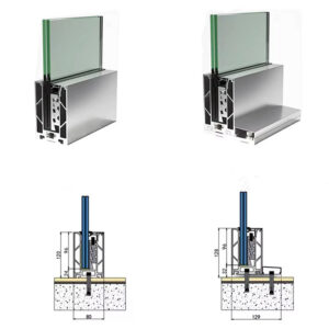
For projects where structural glazing channel integration is part of the cap rail assembly, structural glazing channels designed to coordinate with continuous cap rail profiles can reduce the profile mismatch risk at panel-to-rail transitions. See also The Complete Stainless Steel Glass Railing Guide for Commercial and Residential Projects for a broader specification framework covering material grades, hardware compatibility, and system selection criteria.
The specification decisions that prevent the most costly rework on glass railing cap rail installations are not technical in complexity — they are definitional. Declaring whether the cap rail is structural or protective-only, selecting a profile that meets hand-contact requirements where they apply, and specifying corner treatment and joint method explicitly are each decisions that take minutes at the drawing stage and days or weeks to correct after installation. The fabrication risks at miters, returns, and transitions are real, but they are manageable when shop drawings carry defined tolerances, splice locations, and transition piece requirements based on confirmed field dimensions.
Before procurement or fabrication begins, confirm three things: the functional designation is written into the specification and drives the structural detailing scope; the profile selected matches graspability requirements for all sections requiring hand contact; and corner and joint treatments are specified to a standard the fabricator can be held to, not left to field discretion. Those three confirmations close the gaps that most commonly produce site rejection on continuous cap rail work.
Часто задаваемые вопросы
Q: What happens if the laminated glass in our assembly hasn’t been tested per ASTM E2353 — can we still omit the cap rail?
A: No. The ASTM E2353 exception is the only IBC path to omitting a top rail on glass baluster panels, and it requires documented testing for the specific assembly. If that testing hasn’t been conducted and confirmed for your system, the top rail is required regardless of glass type or how the cap rail is described in the drawings.
Q: After the cap rail specification is finalized, what should happen before fabrication begins?
A: Transition piece dimensions and profile matches should be confirmed from actual field measurements before any cutting or fabrication starts. As-built post geometry and wall conditions routinely differ from design drawings enough to make standard elbows and end caps dimensionally incorrect — confirming from site dimensions, not drawings, removes the assumption that off-the-shelf profiles will fit and prevents the most visible discontinuities in finished work.
Q: Does a continuous cap rail requirement apply to projects outside Florida even when the Florida Building Code isn’t the governing code?
A: The mandatory continuous top rail condition is specific to high-velocity hurricane zones under the FBC, with Miami-Dade being the most common reference. Outside those jurisdictions, the decision depends on whether the glass baluster panel condition or hand-contact condition applies — not on hurricane-zone rules. Projects in other regions still need to evaluate the IBC top rail requirement and graspability thresholds independently.
Q: Is it ever acceptable to use a square cap rail profile if a graspable handrail isn’t explicitly required by code for that location?
A: Yes, provided hand contact is genuinely not required — no stairway handrail obligation, no accessibility mandate, and no project brief requirement for occupant graspability. Where none of those conditions apply, a square or rectangular profile is compliant. The risk is misidentifying the location: if any of those conditions exist and are discovered at inspection, profile replacement or a supplemental handrail is the only correction.
Q: How does a continuous cap rail compare to a fully frameless top edge for a commercial project where barrier performance and aesthetics both matter?
A: A continuous cap rail offers clearer barrier continuity, simplifies panel alignment across long runs, and is the only option where hand contact or the three-panel bridging threshold applies. A fully frameless top edge keeps the view unobstructed but shifts the compliance burden entirely to the glass — requiring laminated glass with documented ASTM E2353 testing, tighter glass-edge tolerances, and no latitude on post-breakage barrier performance. For commercial projects with mixed occupant loads or long panel runs, the continuous cap rail typically reduces total specification and inspection risk even when the frameless look is preferred.