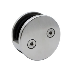
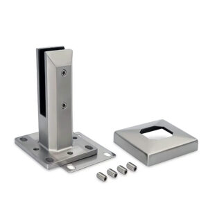
A glass base shoe sits at the junction between the glazing system and whatever structure carries it, which means its supplier cannot quote a channel in isolation from the substrate underneath. Before any anchor spacing or channel dimension can be confirmed, the project team needs to know what the base shoe is actually fixing to, how that construction is built up, and where conflicts between the fixing zone and other embedded elements might already exist. Getting this substrate data wrong does not just slow down a quotation — it can produce a component that fits the glass but not the building.
Substrate facts that change the base-shoe interface
The base shoe’s interface with the supporting construction depends on a small set of substrate facts: the structural material, its condition, the fixing zone available for anchors, and the slab-edge geometry at the mounting line. Each of these changes what the channel can do, independent of the glass it will eventually hold.
Structural material governs how the fixing responds to load and how an anchor behaves once installed. A channel detailed for one structural material does not transfer directly to another, because the anchor-to-substrate relationship is different even if the channel geometry looks the same on a drawing. Where the project substitutes one structural material for another late in design, the base-shoe interface has to be reviewed again rather than assumed to carry over.
Condition matters independently of material type. A substrate that is sound in one area and degraded in another does not offer the same fixing performance across a run, even where the nominal material and thickness are identical. If condition varies along the length of a balustrade line, the fixing zone has to be assessed at each affected section rather than for the run as a whole.
The available fixing zone is the physical space in which anchors can actually be placed without conflicting with reinforcement, embeds, or edge distances. This is a geometric fact about the substrate, separate from the load the channel is expected to carry. A generous structural material does not compensate for a fixing zone that is too shallow or too close to an edge; the two considerations are evaluated separately and both have to be satisfied.
Slab-edge geometry — whether the edge is square, chamfered, stepped, or otherwise formed — determines how the channel’s base plate or leg meets the supporting construction. Where the slab edge condition differs from what the channel was configured for, the seating of the base shoe changes, which in turn affects how the glass line reads along that edge. None of these four facts substitutes for another; a supplier reviewing only one of them is reviewing an incomplete substrate picture.
Drawings needed for slab edges, upstands, and fascia conditions
| Mounting condition | Drawing evidence to provide | Interface the drawing must distinguish |
|---|---|---|
| Top-mounted run | Plans and sections showing the slab edge or upstand condition | How the channel meets the top of the supporting construction |
| Recessed run | Plans and sections showing the recess and adjacent slab-edge or upstand geometry | How the channel seats within the supporting construction |
| Fascia-mounted run | Plans and sections showing the fascia and slab-edge condition | How the channel meets the face of the supporting construction |
The mounting condition — top-mounted, recessed, or fascia-mounted — is not a cosmetic choice; it describes a structurally different interface between the base shoe and the supporting construction, and each one requires its own drawing evidence before a supplier can review fit.
A top-mounted run sits on the upper surface of the slab or upstand, so the drawing has to show that top condition clearly enough to confirm how the channel meets it. A recessed run instead seats within a formed recess, which means the drawing has to show not just the recess dimensions but the adjacent slab-edge or upstand geometry that defines how the channel sits inside it. A fascia-mounted run meets the face of the supporting construction rather than its top or an internal recess, so the relevant drawing evidence shifts to the fascia-to-slab-edge relationship instead.
Where a single project combines more than one of these conditions along different glass runs — for example a top-mounted condition transitioning into a fascia-mounted return — each condition needs its own plan and section, because the interface logic does not carry over from one mounting type to another even within the same job. A plan drawn for a top-mounted assumption does not answer the question a recessed condition raises, and submitting one in place of the other leaves the supplier reviewing an interface that may not match what gets built.
This is also where UFGS 05 52 00 Metal Railings is useful as an example of how a project-specific submittal package can be structured around mounting-condition drawings and plan-and-section evidence, without treating that guide specification as a universal requirement or as something ESANG’s products are certified against. It illustrates the kind of documentation discipline a base-shoe interface review depends on, not a code the supplier enforces.
Fixing-zone conflicts to identify before anchor review
Before any anchor layout is proposed, the fixing zone itself has to be checked for conflicts, because an anchor review that assumes a clear fixing zone is only as good as the information behind that assumption. The two things to check are the size of the available fixing zone and whether known reinforcement or embedded elements already occupy part of it.
An available fixing zone is not simply the dimension shown on a general arrangement drawing; it is what remains once reinforcement, conduit, or other embeds are accounted for. Where reinforcement runs through the zone intended for anchors, the real fixing space is smaller than the nominal dimension suggests, and an anchor layout based on the nominal dimension risks a conflict that only surfaces during installation. This is why identifying known reinforcement or embed conflicts has to happen before, not during, anchor review — a conflict found after the channel has been fabricated to a particular anchor pattern is a different and more difficult problem than one found at the data-gathering stage.
The consequence of an unreviewed conflict is not uniform across projects; it depends on how much margin the fixing zone had in the first place. Where the available zone is generous relative to the anchor pattern, a minor embed conflict may be absorbed by repositioning within the same zone. Where the zone is already tight, the same conflict can force a change to the anchor pattern itself, which then has implications for the channel configuration reviewed against it. This is one reason the fixing-zone question is kept separate from the mounting-condition drawings: a drawing can show the correct mounting condition while still omitting the reinforcement or embed information needed to confirm the fixing zone is actually usable as drawn.
Finish, membrane, and drainage layers crossing the channel detail
| Project information | What the channel detail must show | Interface question |
|---|---|---|
| Finished-floor build-up | The build-up adjoining the channel | How the channel seats relative to the finished floor |
| Waterproofing | The membrane where it crosses or meets the channel detail | Where penetrations can be detailed |
| Drainage | The drainage condition at the channel interface | How drainage is addressed around the channel |
| Edge covers | The cover condition at the slab edge or channel | How the cover relates to channel seating and penetrations |
The channel detail does not exist in isolation from the layers that finish and protect the surrounding construction. Finished-floor build-up, waterproofing, drainage, and edge covers all cross or meet the base-shoe line, and each one changes either how the channel seats or where it can be penetrated.
Finished-floor build-up determines the relationship between the channel and the walking surface once all finish layers are in place, not just the structural slab. Where the build-up is added or changed after a channel has already been selected against the bare structural level, the seating condition shown in the original detail no longer matches what gets installed, and the detail has to be revisited.
Waterproofing is a particular case because it is not just adjacent to the channel — it often has to cross or terminate at the channel line itself, which raises the question of where penetrations through the membrane can be made without compromising its continuity. A channel detail that does not show the membrane’s path at the base-shoe interface leaves that penetration question unanswered, which matters wherever the base shoe sits above or near a waterproofed area rather than purely above dry structural levels.
Drainage at the channel interface is a related but separate concern: even where waterproofing is correctly detailed, the drainage condition determines whether water reaching the base-shoe line is carried away or allowed to pond against the channel. Edge covers — whatever trims or conceals the slab edge or channel — then have to relate correctly to both the channel’s seating and the detailing of any penetrations already established, which means edge covers are reviewed after the seating and penetration questions are settled rather than independently of them. None of these four layers can be substituted for another in the detail; each answers a different interface question, and a detail missing any one of them is incomplete for review purposes.
Responsibility boundary between supplier review and project design
| Party or process | Supported review boundary | What that review does not establish |
|---|---|---|
| Hardware supplier | Component fit and requested evidence | Final anchorage or substrate adequacy |
| Project’s qualified designer | Final anchorage and substrate adequacy | Supplier review alone does not replace project design |
| Project approval process | Project-specific approval of the final design basis | A public standard scope or guide specification alone does not establish project acceptance |
A hardware supplier reviewing a base-shoe submission can confirm component fit and respond to the evidence requested of it, but that review operates within a defined boundary that does not extend to final anchorage or substrate adequacy. Understanding where that boundary sits changes what a buyer should expect from a supplier’s response and what still has to come from elsewhere on the project team.
Component fit review asks whether the channel, as configured, is compatible with the mounting condition, fixing zone, and adjacent layers described in the submitted information. This is a meaningful check, but it is bounded by the accuracy and completeness of what was submitted — a supplier reviewing component fit against incomplete substrate data is reviewing fit against an incomplete picture, not confirming that the installed assembly will perform as intended.
Final anchorage and substrate adequacy are a separate determination, and the inputs place that determination with the project’s qualified designer and its approval process, not with the hardware supplier. This distinction matters because a buyer who receives a positive component-fit response from a supplier should not read that response as confirmation that the anchorage into the actual substrate has been verified; those are different questions answered by different parties.
The same boundary applies to published standards and guide specifications referenced during review. ASTM E2358-24 sets out classification, design, and performance scope for glazing in permanent railing systems, but its public scope summary does not itself establish project acceptance — the detailed requirements and how they apply to a specific project depend on the licensed text and the project’s own authorities, and no inference about ESANG’s compliance should be drawn from citing the standard’s scope. Where a project cites a guide specification such as UFGS 05 52 00 as a reference for submittal structure, that reference illustrates a documentation approach; it does not substitute for the project’s own design basis or approval process. The practical effect is that a buyer gathering substrate information is not just feeding a supplier’s quotation — that same information is what the project’s qualified designer needs to close the anchorage and substrate-adequacy questions that sit outside the supplier’s review.
Data package that makes quotations technically comparable
| Data group | Common information to give each supplier | Comparison check |
|---|---|---|
| Supporting construction | Structural material, condition, available fixing zone, and slab-edge geometry | Are the quotations based on the same substrate condition and fixing space? |
| Mounting interface | Top-mounted, recessed, or fascia-mounted condition shown in plans and sections | Are the quotations reviewing the same channel-to-support interface? |
| Known conflicts | Known reinforcement or embed conflicts | Has each supplier reviewed the same identified fixing-zone constraints? |
| Adjacent construction | Finished-floor build-up, waterproofing, drainage, and edge covers | Are the quotations based on the same channel seating and penetration context? |
| Design basis and evidence | Project design basis and the evidence requested for review | Do the quotations state component fit and evidence against the same project basis without implying final anchorage or substrate approval? |
Once the substrate facts, mounting-condition drawings, fixing-zone conflicts, and adjacent-layer details have been gathered, the remaining question is whether that information is given to every quoting supplier in the same form. Quotations are only comparable if each supplier is reviewing the same substrate condition, the same interface, the same known conflicts, and the same design basis — not simply the same channel product.
Where one supplier receives full plans and sections for a recessed condition and another receives only a general arrangement drawing, their quotations are not answering the same question, even if both reference the same base shoe product line. The difference is in what each supplier was asked to review, not in the products themselves. The same applies to known reinforcement or embed conflicts: if that information is given to one supplier and withheld from another, one quotation reflects an informed review of the fixing zone and the other does not, and comparing them directly overstates the similarity between the two responses.
This is also where a buyer’s own submitted information enters supplier-side configuration and quotation review directly — the structural material, fixing zone, mounting condition, and adjacent-layer details the buyer provides become the basis against which a channel such as those in ESANG’s glass base shoe channels or structural glass base rails ranges would be reviewed for fit, so the completeness of that submission has a direct bearing on how meaningful the resulting quotation is.
A design basis stated consistently across all quoted suppliers also keeps the evidence each one requests aligned to the same project question. Where one supplier is told the project design basis and asked to state component fit against it, and another is left to infer the design basis from a partial drawing set, their resulting evidence packages answer different scopes of question even when both avoid overstating final anchorage or substrate approval. Confirming that every supplier received the same substrate package, mounting-condition evidence, conflict disclosure, and design-basis statement is what allows the resulting quotations to be judged against each other rather than against whatever assumptions each supplier filled in independently.
Frequently Asked Questions
Q: What should I do if some substrate information is not final when requesting a quotation?
A: Mark each unresolved item as provisional rather than leaving it implicit. Give every supplier the same known structural material, slab-edge geometry, fixing zone, mounting condition, and adjacent construction, then ask each quotation to state the assumptions used; confirm the open items before final anchorage review.
Q: Can one substrate detail be used for top-mounted, recessed, and fascia-mounted base-shoe runs?
A: Only if it clearly distinguishes each mounting condition. Provide plans and sections for every condition because the channel meets the supporting construction differently at the top, within a recess, and at the slab face.
Q: Why must the supplier see floor finishes, waterproofing, drainage, and edge covers?
A: These layers affect how the channel seats and where penetrations can be detailed. Show how each layer meets or crosses the channel so the component review reflects the intended finished interface rather than an incomplete substrate condition.
Q: Does the base-shoe supplier confirm that the substrate and anchors are adequate?
A: No. The supplier can review component fit and the evidence requested, while final anchorage and substrate adequacy remain with the project’s qualified designer and approval process.
Q: Does referencing ASTM E2358-24 or UFGS 05 52 00 establish project acceptance?
A: No. ASTM E2358-24 provides a scope for permanent railing glazing, and UFGS 05 52 00 is an example guide specification; the applicable licensed requirements, project design basis, and approval process still need to be identified for the project.