Specifying cable railing posts for a multi-story commercial building is a structural engineering challenge, not an aesthetic choice. The primary risk is underestimating the forces at play—cumulative cable tension, concentrated live loads, and dynamic wind pressure—leading to a system that is non-compliant or, worse, unsafe. Misclassifying post types or anchoring to non-structural elements are common, costly errors.
For architects and engineers, this topic demands attention because the liability is permanent. A railing is a life-safety system governed by strict codes. The engineering decisions made during specification—material selection, load path, and connection design—directly impact the building’s long-term integrity, maintenance liability, and occupant safety. Getting it wrong is not an option.
Key Engineering Differences: Terminal vs. Intermediate Posts
Defining the Structural Roles
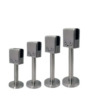
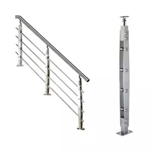
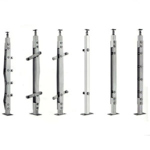
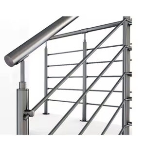
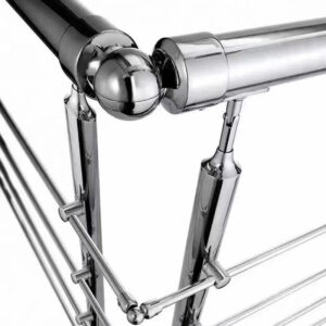
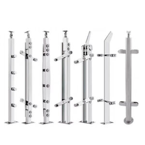
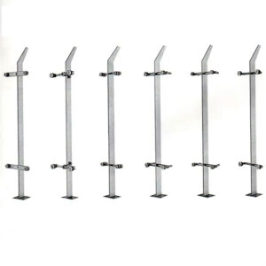
The system’s integrity hinges on correctly classifying terminal and intermediate posts. This classification dictates every subsequent engineering decision, from post size to anchoring. Terminal posts, located at ends and corners, are the structural anchors. They must resist the cumulative tensile pull of all cables, which can exceed several thousand pounds, creating significant bending and overturning moments.
Intermediate posts serve a fundamentally different purpose. Their primary role is not to handle terminal tension but to control lateral deflection. They maintain cable spacing and, critically, limit sway to comply with the mandated 4-inch sphere rule. Spaced at a maximum of 48 inches on center, they ensure the infill acts as a continuous guard. Misclassifying a post during the layout phase is a fundamental error that compromises the entire system’s design.
Application in System Layout
This bifurcation directly impacts project planning and cost. A terminal post requires robust construction, typically schedule 80 pipe or heavy-wall tubing, and a specialized, engineered anchor designed to resist overturning. An intermediate post, while still substantial, can often be of lighter construction since its axial load is minimal.
From experience, the most efficient projects begin with a detailed post layout map that clearly labels every terminal and intermediate post. This map becomes the foundational document for structural calculations and fabrication. Overlooking a corner or a change in direction, which forces a cable run to terminate, can inadvertently turn an intended intermediate post into a de facto terminal post without the required strength.
Impact on Design and Cost
The structural role directly influences material and fabrication costs. Specifying a heavy-wall terminal post where an intermediate post would suffice is an unnecessary expense. The far greater risk is the inverse: an under-designed terminal post that cannot handle the load. This often leads to costly field modifications, delays, and potential redesign.
The choice also affects hardware. Terminal posts require moment-resisting bases, while intermediate posts may use simpler sleeker mounts. Understanding this distinction allows for optimized specification, ensuring safety and code compliance without over-engineering and overspending.
| Post Type | Primary Structural Load | Key Design Driver |
|---|---|---|
| Terminal Post | Full cable tension (~350 lbs/cable) | Resist overturning & bending |
| Intermediate Post | Lateral deflection control | 4-inch sphere rule compliance |
| Terminal Post | Several thousand pounds cumulative | Heavy-wall tubing required |
| Intermediate Post | Minimal axial load | 48-inch maximum spacing |
Source: Technical documentation and industry specifications.
Structural Load Calculations for Commercial Cable Railings
Code-Mandated Live Loads
The International Building Code (IBC) governs the primary live loads. The most critical is the requirement that the top rail resist a concentrated load of 200 pounds applied in any direction. This tests the combined strength of the posts, their connections to the top rail, and the top rail itself. This load is not theoretical; it simulates a person falling against the rail.
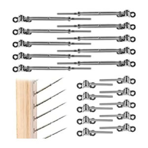
A second, often underestimated load is the continuous cable tension. Each cable is typically tensioned to approximately 350 pounds to minimize sag and vibration. On a terminal post with ten cables, that’s a constant 3,500-pound tensile pull. This is not a live load per code but a permanent operational load that the post and its anchor must withstand indefinitely without creep or deformation.
The Engineering Process
These loads are combined and analyzed by a licensed structural engineer. They perform calculations to determine the required post size, wall thickness, and section modulus. The engineer considers load combinations, including tension plus lateral load, to ensure the post will not yield or deflect excessively. The section modulus, a geometric property of the post’s cross-section, is crucial for resisting bending.
The engineer’s stamp is not a formality; it is a legal certification of safety. They verify that the specified components, from the stainless steel tubing to the bolts, create a continuous load path capable of transferring all forces into the building’s primary structure. Guessing at these specifications is a profound professional and legal risk.
Validating the Load Path
The calculations are meaningless without validation at the connection points. The mounting hardware—whether a flange, bracket, or embedded plate—must be engineered to distribute the overturning moment and shear. The attachment must be to a structural element: a concrete slab, steel beam, or engineered wood member. Anchoring to decking, fascia, or veneer is a common and dangerous mistake.
We’ve reviewed projects where beautiful railing designs failed because the elegant, hidden mounting hardware lacked the structural capacity to transfer the load. The engineering must be holistic, from the cable tip to the building’s skeleton. The table below summarizes the key loads that drive this analysis.
| Load Type | Code Requirement | Key Consideration |
|---|---|---|
| Concentrated Live Load | 200 pounds, any direction | Top rail & post strength |
| Cable Tension (per cable) | ~350 pounds | Cumulative terminal post load |
| Design Verification | Licensed structural engineer | Post size & wall thickness |
| Connection Load Path | Into primary structure | Engineered attachments required |
Source: Technical documentation and industry specifications.
Wind Load Analysis and Code Compliance for High-Rise Railings
Code as the Foundation
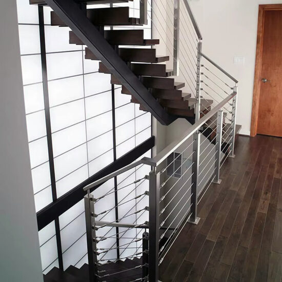
Compliance with the International Building Code (IBC) and local amendments is non-negotiable. The IBC sets the minimum guard height (42 inches) and the infill opening limit (the 4-inch sphere rule). For cable railings, this rule is the primary geometric driver, typically mandating cable spacing at 3 inches or less. It also dictates the maximum unsupported cable span, which is why intermediate posts or cable braces cannot exceed 48 inches on center.
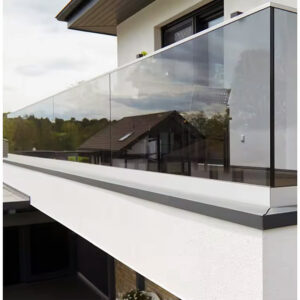
These are baseline requirements. For multi-story buildings, the dynamic force of wind often becomes the governing design load. Wind pressure increases with height and exposure, creating a pushing force on the cable infill that transfers as a lateral load to the posts, inducing high bending moments at their base.
Performing Wind Load Analysis
Wind load is determined using ASCE 7 Minimum Design Loads and Associated Criteria for Buildings and Other Structures. This standard provides the methodology to calculate design wind pressures based on the building’s geographic location, height, exposure category (urban, suburban, open), and importance factor. The railing system, as a component, must be designed to resist these pressures.
An engineer will calculate the wind load on the railing’s projected area and ensure the posts and anchors have sufficient capacity. The goal is to prevent excessive deflection that could alarm occupants, permanent deformation, or connection failure. On a high-rise balcony, the wind load can be an order of magnitude greater than the code-mandated 200-pound concentrated load.
Compliance Verification
The verification process synthesizes all requirements. The system must simultaneously comply with the 4-inch sphere rule under no load, resist the 200-pound concentrated load, and withstand the calculated wind pressures without failure. This often leads to specifications for thicker wall tubing, closer post spacing, or more robust anchoring for posts on upper floors.
| Parameter | Code/Design Standard | Typical Specification |
|---|---|---|
| Infill Opening Limit | IBC 4-inch sphere rule | 3-inch cable spacing |
| Maximum Cable Span | IBC deflection control | 48 inches unsupported |
| Minimum Guard Height | IBC Section 1015 | 42 inches |
| Load Basis | ASCE 7 wind maps | Building height & location |
Source: ASCE 7 Minimum Design Loads and Associated Criteria for Buildings and Other Structures. This standard provides the minimum wind, seismic, and live loads that railing posts and attachments must resist, forming the basis for code-compliant engineering analysis.
Post Material Specifications: 316 Stainless vs. Coated Carbon Steel
Evaluating Corrosion Resistance
For exterior multi-story applications, material selection is a lifetime cost decision. Type 316 stainless steel contains molybdenum, which provides superior resistance to pitting and crevice corrosion, especially from chlorides in coastal air or de-icing salts. It is the industry standard for harsh environments because it maintains its structural integrity and appearance with minimal maintenance—often requiring only periodic washing.
Coated carbon steel (e.g., powder-coated or galvanized) offers a higher strength-to-cost ratio upfront. However, it introduces a lifecycle liability. Any breach in the coating—from fabrication, installation, or impact—becomes a corrosion site. In demanding environments, this necessitates a long-term plan for inspection, touch-up, and eventual recoating, adding operational expense and downtime.
Structural and Fabrication Properties
Both materials must meet structural requirements. Stainless posts are typically fabricated from welded mechanical tubing conforming to standards like ASTM A554 Standard Specification for Welded Stainless Steel Mechanical Tubing, which ensures consistent chemical and mechanical properties. Common specifications for commercial posts are schedule 80 pipe or round tube with a minimum 0.125-inch wall, with 0.25-inch wall often specified for high-load scenarios to achieve the necessary section modulus.
Carbon steel can be fabricated to similar dimensions and offers high strength. The critical difference is not in its load-bearing capacity but in its long-term durability at the connection points and in hidden areas where moisture can accumulate. For concealed posts or interior atriums, carbon steel can be a viable option. For exposed exteriors, it represents a calculated risk.
The Decision Framework
The choice hinges on three factors: environmental exposure, aesthetic permanence, and total cost of ownership. In aggressive environments, the lifetime cost of maintaining carbon steel often surpasses the higher initial investment in 316 stainless. Specifying stainless steel is an investment in asset preservation, reducing long-term liability and preserving the design intent. The table below outlines the core differentiators.
| Material | Corrosion Resistance | Typical Wall Thickness |
|---|---|---|
| 316 Stainless Steel | Excellent (chloride resistant) | 0.125″ min, 0.25″ common |
| Coated Carbon Steel | Requires maintenance | Varies by coating system |
| 316 Stainless Tubing | Schedule 80 pipe | High section modulus |
| Application Fit | Harsh environments | Long-term asset preservation |
Source: ASTM A554 Standard Specification for Welded Stainless Steel Mechanical Tubing. This standard covers the welded stainless steel mechanical tubing commonly used for architectural and structural members like cable railing posts, specifying chemical composition and mechanical properties.
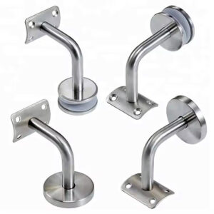
Mounting and Anchoring Solutions for Structural Integrity
Mounting Method Options
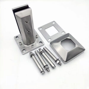
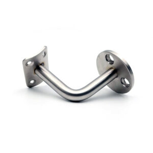
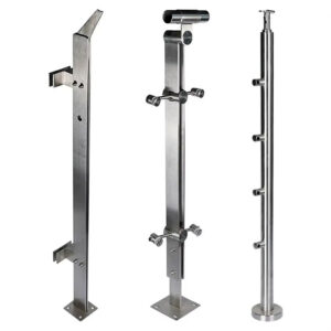
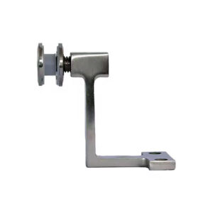
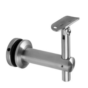
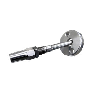
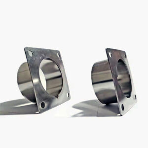
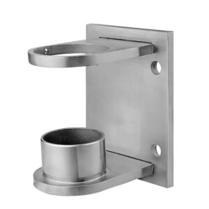
The three primary methods—deck (surface), fascia (side), and wall mount—each affect the load path and aesthetic. Deck mounts are the most straightforward for load transfer, typically using a heavy-duty flange through-bolted to the structure. Fascia mounts offer a cleaner look by hiding the base plate but require careful engineering to resist the increased lever arm and overturning moment. Wall mounts are common for balconies and terraces.
The choice is not purely aesthetic. Each method applies forces differently to the building structure. A fascia-mounted post creates a significant prying action on the fascia attachment. The building’s design must accommodate this, requiring early coordination between the railing engineer and the building’s structural engineer to ensure adequate reinforcement is in place.
Engineering the Connection
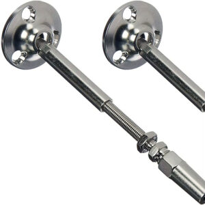
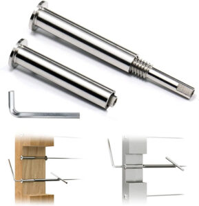
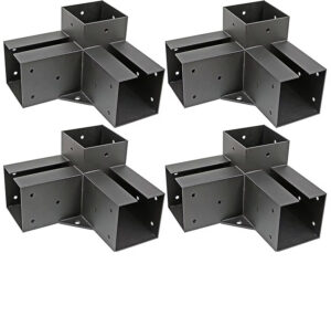
This interface is the system’s potential failure point. Hardware must be designed to create a moment-resisting connection. Long-neck flanges, reinforced gusseted brackets, or embedded weld plates are standard. They must be secured with high-strength mechanical anchors or epoxy-set threaded rods into concrete, or directly welded to steel framing.
The principle is to avoid “bolt-in-shear” connections for terminal posts, which are weak in overturning. The hardware must engage multiple bolts or a weld pattern to distribute the load. We specify and supply proprietary anchoring solutions precisely because generic hardware from a local supplier is invariably inadequate for the calculated moments in a commercial setting.
Ensuring Continuous Load Path
The final step is verifying that the attachment point is a primary structural element. This often requires reviewing construction documents or conducting field probes. Anchoring to composite decking, thin precast panels, or brick veneer is structurally invalid. The mounting strategy, therefore, must be locked in during the design development phase, not as a field fix. The building structure itself must be part of the railing specification.
How to Specify Cable Railing Posts for Your Project
Developing the Specification Document
Begin with a comprehensive set of engineered drawings, not just architectural elevations. These should include a post layout plan, detailed sections at all conditions (terminations, corners, gates), and connection details. The specification section must explicitly call out:
- Material: e.g., “Type 316 stainless steel, ASTM A554, Schedule 80, 0.25″ wall.”
- Post Classification: Clear designation of terminal vs. intermediate on plans.
- Fabrication Tolerances: For weld quality, squareness, and finish.
- Hardware: Specify grade of all fasteners and anchors.
A critical, often overlooked constraint is cable geometry. The 1×19 construction used for stability is semi-rigid and cannot bend around a corner. Any change in direction requires a terminal post, which fundamentally shapes the layout of complex balcony shapes or stair cascades.
Supplier Selection Strategy
The market splits between kit suppliers and custom engineering fabricators. For multi-story commercial work, the complexity demands a full-service partner. Key evaluation criteria include in-house engineering capability (PE stamp), local fabrication capacity for shorter leads and site adaptability, and a portfolio of similar-scale projects.
Local fabrication is a strategic advantage. It allows for easier handling of last-minute field dimensions, site visits, and quicker turnaround for replacements or modifications. It also facilitates better coordination during the critical installation phase.
Lifecycle and Maintenance Planning
Specification should extend beyond installation. Include requirements for the supplier to provide maintenance guidelines, recommended cleaning agents for the specified finish, and availability of matching components for future repairs or expansions. For stainless steel, this includes guidance on passivation treatments if the posts are welded or modified on-site, to restore the protective oxide layer.
Request a Quote for Engineered Cable Railing Posts
Preparing for an Accurate Quote
To receive comparable and meaningful quotes, provide vendors with a complete package. This includes architectural drawings with railing layouts, structural drawings showing potential attachment points, and project specifications. Also include the project location (for wind/seismic data), building height and exposure, and intended use (e.g., public rooftop bar, hotel balcony).
Clearly state your needs: Are you requesting a design-build package including engineering stamps, or will you provide stamped drawings? Define material preferences and any critical aesthetic or finish requirements. Ambiguity here leads to quotes with broad exclusions or hidden costs for later engineering.
Evaluating the Proposal
A detailed quote should be transparent. It should itemize material costs (posts, cable, fittings, hardware), fabrication labor, engineering fees, and any site measurement services. Scrutinize the engineering scope: does it include review of your attachment details, or just the railing assembly? Clarify lead times and the process for handling RFIs and shop drawings.
For complex projects, prioritize vendors who ask detailed questions about the structure and load path. This demonstrates the necessary engineering mindset. The goal is to select a partner who ensures the railing is a code-compliant, integrated structural system, not just a supplied commodity.
The specification of cable railing posts requires a disciplined, code-first methodology. Prioritize the accurate classification of terminal and intermediate posts, as this drives all structural calculations. Second, secure engineering oversight early to validate the load path from cable to primary structure, especially for wind loads at height. Third, make material selections based on total lifecycle cost, not initial price, to ensure durability and minimize long-term liability.
Need professional engineering and fabrication for your commercial railing system? Esang provides full-service design, stamped calculations, and precision fabrication for multi-story projects. Contact us to discuss your specifications and project timeline.
For a direct consultation, you can also Contact Us.
Frequently Asked Questions
Q: What are the key structural differences between terminal and intermediate posts in a commercial cable railing system?
A: Terminal posts must withstand the full cumulative tension from all cables, which can exceed several thousand pounds, requiring heavy-wall tubing and engineered anchoring to resist overturning. Intermediate posts primarily control lateral cable deflection to meet the 4-inch sphere rule, with a maximum spacing of 48 inches on center. This means your project’s post layout plan is critical, as misclassifying a post type leads to structural inadequacy or expensive field corrections.
Q: How do you calculate wind loads for cable railings on a high-rise building?
A: Wind load analysis is mandatory for multi-story applications and involves calculating dynamic lateral pressure based on building height, location, and exposure. An engineer uses these forces to ensure posts and connections prevent excessive deflection or failure under code-prescribed conditions. For projects in high-wind zones, you must budget for professional design services to meet ASCE 7 load requirements and local code amendments.
Q: When should we specify 316 stainless steel over coated carbon steel for exterior cable railing posts?
A: Type 316 stainless steel is the standard for harsh environments due to its superior chloride resistance, ensuring longevity with minimal upkeep. Carbon steel with coatings offers a lower initial cost but introduces lifecycle expenses for inspection and recoating. For coastal buildings or areas using de-icing salts, the higher upfront investment in stainless, often using tubing per ASTM A554, is justified as an investment in asset preservation.
Q: What mounting methods ensure structural integrity for commercial cable railing posts?
A: Integrity depends on through-bolting heavy-duty hardware like floor flanges or rectangular brackets directly to primary structural elements—concrete slabs or steel beams—using high-strength anchors. The connection must be designed as a moment-resisting joint to distribute overturning and shear forces. This means your architectural team must coordinate mounting strategy early to confirm the building structure can provide the necessary verified load path.
Q: How does the 4-inch sphere rule impact the design of a cable railing system?
A: This code rule mandates that a 4-inch sphere cannot pass through any opening in the guard infill. It directly dictates a maximum cable spacing of typically 3 inches and limits the unsupported cable span between posts to 48 inches. For your project, this rule determines the required number of cables and intermediate supports, making it a primary driver for system geometry and material quantities.
Q: What information is essential for requesting an accurate quote on engineered cable railing posts?
A: Provide comprehensive project data: architectural drawings with railing layouts, building location and height, material preferences, and finish requirements. Crucially, specify if you need full engineering services or will supply stamped drawings. For complex multi-story projects, you should prioritize vendors with local fabrication and a proven track record, as their quotes will reflect realistic lead times and capacity for field coordination.
Q: Why is a post layout map the first critical step in specifying a cable railing system?
A: A detailed layout classifies every post as terminal or intermediate, which dictates its required size, wall thickness, and anchoring. Terminal posts handle all cable tension, while intermediate posts manage deflection. If your project has complex geometries with corners, remember that semi-rigid cable cannot bend sharply, forcing runs to terminate at additional terminal posts—a constraint that must be mapped from the start to avoid costly redesigns.