Most hardware selection problems in cable railing show up at commissioning, not during procurement. A tensioner that passed every paper check can still fail its first real test when the installer discovers the adjustment mechanism cannot be reached with available tools inside a confined post cavity — and the only correction is post removal or a visible field modification that compromises the finished detail. That discovery, at commissioning, after the frame is set and cable is run, is substantially more expensive than the same discovery at mockup. The judgment this guide is organized around is simple: hardware selection for cable railing is a geometry and access problem before it is a product specification problem, and the sequence in which those problems are resolved determines whether the installation closes cleanly or accumulates callbacks.
The Selection Variables Contractors Must Fix First
Before specifying any tensioner or terminal, the geometry of the system has to be resolved — because the wrong answers to these foundational questions don’t just create installation difficulty, they constrain which hardware can work at all. Post spacing, cable count, railing height, and fitting type all interact. Change one variable late and the adjustment range required from the tensioner may shift beyond what the selected hardware can deliver.
The railing height thresholds most jurisdictions reference — 36 inches for residential applications, 42 inches for commercial — and the guardrail trigger at 30 inches above grade are starting conditions, not afterthoughts. They define cable run length and, combined with post spacing, determine how many cables are needed and how much tensioner travel each run requires. Post spacing up to 48 inches center-to-center is a common planning ceiling; beyond that, cable deflection under lateral load becomes difficult to control. Cable spacing of approximately 3 inches — sized to prevent a 4-inch sphere from passing through — drives cable count directly, and cable count drives the total adjustment demand on the system. These thresholds should be confirmed against the local authority having jurisdiction before hardware is ordered, since local amendments can vary.
The fitting type decision — swageless for straightforward level runs, turnbuckle-style adjustment for stairs and complex angles — is not a preference question. It is a consequence of run geometry. A swageless fitting on a stair run that was never designed to accommodate it is an adjustment problem waiting to surface after the first season. Getting the geometry resolved first means hardware selection narrows to a short list of options that can actually work, rather than starting from catalog and discovering mismatches on site.
| Selection Parameter | Requirement or Threshold | Why It Matters |
|---|---|---|
| Tensioner placement | Install a tensioner at both ends of each cable run | Doubles adjustment range; prevents losing thread engagement during tensioning or after cable settling |
| Guardrail trigger height | Guardrail required when deck surface ≥ 30 in above ground | Avoids safety hazard and code violation from missing guardrail |
| Railing height | 36 in (residential); 42 in (commercial) | Code‑mandated height; non‑compliance creates safety and legal risk |
| Max post spacing | 48 in center‑to‑center | Exceeding spacing leads to cable deflection beyond code limits |
| Cable spacing | Approx. 3 in apart; 4‑in sphere must not pass through | Child safety code; affects cable count and tensioner travel needed |
| Fitting type by geometry | Swageless for simple level decks; turnbuckles for stairs or complex layouts | Wrong choice causes difficult installation or inadequate adjustment range |
The order of operations matters here. Contractors who select hardware before confirming post spacing, cable count, and run geometry often find that the tensioner’s available thread travel is consumed just achieving initial tension — with nothing left for the adjustment that cable settling and temperature cycling will demand in the first year.
Tensioner Travel and Post Access at Each Termination
Thread travel and physical access are two separate constraints, and both have to be satisfied at the same termination point. A tensioner with adequate adjustment range is still non-functional if the tool required to operate it cannot reach the mechanism from the accessible side of the post.
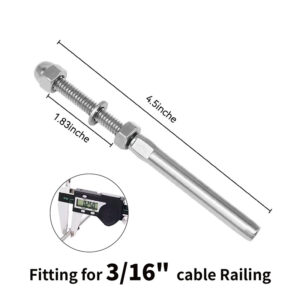
Post cavity geometry sets the first boundary. A terminal designed for internal installation inside a 2×2 metal post occupies that cavity in three dimensions — length, diameter, and tool clearance — and all three have to fit before the fitting is considered viable for that post. The 2-inch terminal length figure referenced for one category of swageless fittings is a product-specific planning criterion, not a universal industry standard; other terminals have different body lengths and clearance requirements. What applies universally is the logic: measure the cavity, confirm the terminal fits, then confirm the tool can operate inside it. A 3/16-inch Allen wrench is a relatively compact tool, but even that can be blocked by an insufficiently deep cavity or a post wall that limits the wrench’s swing angle. The specific tool requirement should be verified against the actual fitting being specified, not assumed.
Re-tensioning capacity over time is the constraint that gets underestimated most consistently. Turnbuckles allow re-tightening without disassembly months or years after installation, which is a real operational advantage on runs that will need periodic adjustment. The trade-off is that exposed threads collect contamination — particularly in coastal or high-humidity environments — and that contamination accelerates corrosion and can prevent future adjustment. Swageless fittings avoid exposed thread problems but have limited re-tensioning travel once locked at initial installation, which means the access plan for future adjustment has to be built into the design before installation, not addressed reactively when cables begin to sag. For angled or stair runs, beveled washers and precise hole alignment are prerequisites regardless of fitting type; misalignment at the post translates directly into binding under tension.
| Termination Check | What to Confirm | Risk if Not Addressed |
|---|---|---|
| Post‑cavity fit | Terminal length and diameter fit inside the post cavity (e.g., 2 in length for 2×2 metal posts) | Terminal interference forces post modification or substitution |
| Tool access for tensioning | Required tool (e.g., 3/16 in Allen wrench) can reach and operate inside the cavity or from the accessible side | Inability to tension or adjust; hidden post damage |
| Re‑tensioning allowance after install | Mechanism allows future re‑tightening without disassembly (turnbuckle) or limited‑travel access plan (swageless) | Permanent sagging when cables stretch or temperatures change |
| Post material and angle | Push‑Lock Tensioner with Threaded Clevis for metal, Lag Clevis for wood; beveled washers and accurate drilling for stairs/pitched runs | Misalignment, binding, and uneven tension leading to failure |
| Corrosion and exposure risk | Exposed threads on turnbuckles collect dirt; coastal environments accelerate corrosion | Weakened connection over time |
The failure mode that this section is designed to prevent is discovering at commissioning that the terminal is physically installed but cannot be adjusted — either because the tool doesn’t fit, the thread travel is already exhausted at initial tension, or the run angle was never accommodated at the drilling stage. None of these problems are recoverable without disassembly.
Swageless Assembly Versus Factory‑Swaged Control
The choice between swageless fittings and factory-swaged terminals is an engineering and procurement trade-off across four dimensions: tool cost, workflow sequence, error forgiveness, and long-term serviceability. Neither option is categorically superior; the right answer depends on project scale, site conditions, and the crew’s existing equipment.
Swageless fittings eliminate the hydraulic swaging tool from the equipment list entirely. On a small project where no swaging tool is already owned, that tool cost — whether purchased or rented — can offset the higher per-piece cost of swageless hardware before the first cable is run. The more operationally significant advantage is workflow: swageless fittings can be installed in parallel with frame assembly because measurements don’t need to be finalized before the cable is cut. A swaged terminal, by contrast, requires the run length to be measured accurately before crimping, and a measurement error means the cable and the fitting are both lost. That permanence is the central risk of swaged assembly in field conditions where dimensions can shift as the frame is set and leveled.
The serviceability difference becomes relevant over a longer horizon. Swageless fittings that disassemble cleanly allow cable replacement or post relocation without cutting, which reduces disruption and hardware cost on future modifications. A swaged terminal cannot be removed without cutting; any service that requires disassembly means new hardware and a new crimp. For projects where future reconfiguration is plausible — phased commercial builds, installations in spaces that may be repurposed — that lifecycle difference has real procurement implications.
Cable specifications under both assembly methods are governed by the same underlying wire rope and rope wire material requirements. ISO 2408:2017 and ASTM A492-95(2004) establish the material basis for stainless steel wire rope and rope wire respectively; those standards apply to the cable itself regardless of how the terminal is attached. The assembly method changes the installation workflow and serviceability profile, not the cable’s structural requirements.
| Aspect | Swageless Fittings | Factory‑Swaged (Crimped) Fittings |
|---|---|---|
| Tool requirement | No hydraulic swaging tool; standard hand tools | Hydraulic swaging tool required (purchase/rental) |
| Measurement flexibility | Adjustable during assembly; works in parallel with frame build | Requires precise pre‑assembly measurement; cut‑and‑discard if wrong |
| Error forgiveness | Reusable and adjustable; field mistakes can be corrected | Permanent; measurement error destroys cable and fitting |
| Workflow sequence | Can be installed simultaneously with railing frame | Must complete measurement, cut, and crimp before final assembly |
| Serviceability | Disassembles cleanly years later; enables cable replacement or post relocation | Fitting cannot be removed without cutting; new hardware and crimp needed |
| Total cost | Higher per‑piece cost; no swaging tool expense, often lower total for small projects | Lower per‑piece cost; swaging tool investment adds to upfront cost |
For larger projects with multiple crews and an owned swaging tool already in service, the per-piece cost difference favors swaged terminals and the workflow discipline required is manageable. For smaller jobs, the swageless path consistently outperforms on total installed cost once tool expense and error recovery are included. Contractors who don’t run that comparison explicitly tend to default to the option that looks cheaper on the hardware line item and absorb the difference elsewhere.
Esang’s swageless cable tensioners and cable tensioner systems are configured for this range of project conditions — the right starting point depends on the scale and site variables described above.
Field Failures Caused by Incompatible Terminals
Incompatible terminal selection rarely produces an immediate, obvious failure. It produces a pattern of installation-stage decisions that compound into a system that either cannot be tensioned correctly at commissioning or degrades below acceptable performance within the first year. Understanding the mechanism behind each failure pattern is more useful than a list of things to avoid.
Over-tightening and under-tensioning are mirror failure modes with a shared cause: the installer has no reliable reference for where correct tension actually sits. Over-tightening swageless tensioners past their designed load range risks deforming the body or threads, which is not always visible at installation but surfaces as binding or failure during the first re-tension attempt. Under-tensioning leaves cable spacing that may look acceptable at initial inspection but widens as cables settle, potentially opening gaps beyond the 3-inch spacing threshold without any hardware change. Both failures trace back to the absence of a calibrated tensioning reference for the specific fitting and cable combination in use.
Corrosion and alignment failures are often attributed to the environment when the actual cause is installation prep. Cables that are not cleaned before fitting assembly carry surface contamination into the terminal interface, which accelerates corrosion at the contact point and can create uneven load distribution across the wire strands. Fitting misalignment — particularly at angled runs where drilling precision is critical — creates a bending load at the terminal entry that the fitting was not designed to carry, concentrating stress and shortening service life. These are not swageless-specific problems; they apply to any terminal type and are more likely to appear when installation moves quickly and prep steps are skipped.
Turnbuckle binding deserves separate attention because it can block re-tensioning entirely. A turnbuckle that was not precisely aligned at initial installation may load unevenly across its barrel, making rotation progressively harder as tension increases. In coastal or wet environments, thread contamination accelerates this problem — the turnbuckle that could theoretically re-tension the cable becomes mechanically locked before the adjustment is complete. The failure is not the hardware design; it is the gap between the hardware’s maintenance requirement and the site conditions it was installed into.
| Failure Risk | What Causes It | Consequence |
|---|---|---|
| Over‑tightening damage | Excessive tension applied to swageless tensioners | Deformation or failure of tensioner components |
| Under‑tensioning | Insufficient tension left in cable runs | Loose, unstable railing; safety and code violation |
| Corrosion and uneven loading | Misaligned fittings; cables not cleaned/prepped before assembly | Early corrosion and uneven load distribution shorten system life |
| Turnbuckle binding / corrosion | Misalignment causing binding; exposed threads collect dirt in coastal or outdoor settings | Tension adjustment blocked; thread corrosion weakens the connection |
| Persistent cable sag | Terminal design limits re‑tensioning; temperature swings cause expansion/contraction | Cables sag below code‑required tension; potential liability |
Temperature-driven cable movement is the failure pattern most likely to produce a code-adjacent outcome without any visible installation defect. Cable expansion and contraction across seasonal temperature swings creates slack that accumulates over the first year. A system that was properly tensioned at installation but has no usable re-tensioning path — because thread travel was exhausted, access is blocked, or hardware type doesn’t permit it — can sag to non-compliant cable spacing with no identifiable cause other than the original hardware selection not accounting for this adjustment demand. Planning for a re-tension check after the first season is the standard way to close this risk.
For a broader reference on cable specification and system planning, the Complete Stainless Steel Cable Railing Guide covers material grade selection, corrosion considerations, and installation context in more detail.
Mockup Checks Before Hardware Approval
The cost of running a mockup check before hardware approval is a fraction of the cost of correcting the same problem after installation is underway. That asymmetry is the only argument needed for treating these checks as standard practice rather than optional due diligence — but the mechanism behind it matters, because it clarifies what the mockup is actually testing.
A mockup connection tests geometry and access together under real conditions. The terminal either fits the post cavity or it doesn’t. The tool either reaches the adjustment mechanism or it doesn’t. Thread engagement either allows the tension range the run requires or it runs short. None of these checks can be reliably substituted by reviewing catalog specifications alone, because post cavity dimensions, finish details, and wall thickness vary in ways that product data sheets don’t fully capture. A terminal that is specified as 2 inches long for a 2×2 metal post still has to clear any internal weld bead, drainage slot, or finish collar in that specific post profile.
Washer selection is a check that frequently gets omitted from mockup verification even though the consequence — galvanic corrosion or terminal misalignment — develops slowly enough that it isn’t attributed to the installation error. A Delrin washer at a metal post protects the post face and provides electrical isolation; a stainless-steel washer at a wood post maintains alignment under the compressive load of the terminal. Using the wrong material at either post type creates a corrosion initiation point that is embedded in the assembly and not accessible for inspection without disassembly.
| Mockup Check | What to Verify | Why It Matters |
|---|---|---|
| Terminal fit in post cavity | Physical terminal fits inside intended post cavity (e.g., 2 in long for 2×2 metal posts) | Non‑fitting terminal forces post modification or hardware return |
| Tool availability and access | All required tools (drill, level, tape, wrenches, cable cutter; no swager needed for swageless) are on site and can reach the cavity | Missing tools stall work and may lead to unsafe improvised methods |
| Tensioning sequence | Tension from middle cables outward, alternating up/down to spread load evenly | Incorrect order causes uneven tension and possible frame distortion |
| Washer material | Delrin washer for metal posts, stainless‑steel washer for wood posts | Prevents galvanic corrosion and maintains alignment |
| Re‑tension plan | Confirm a follow‑up tension check is scheduled after the first season to address settling and temperature changes | Avoids sagging below code and potential liability |
Tensioning sequence and the re-tension plan are process decisions, not hardware decisions, but they belong in the mockup review because they affect whether the hardware selection holds up over time. Starting tension from the middle cables and working outward — alternating up and down — distributes the load progressively and prevents the frame distortion that sequential tensioning from one end can create. Scheduling a re-tension check after the first season addresses the cable settling and temperature cycling that are predictable in nearly every installation, and converts a common liability exposure into a managed maintenance step. Neither of these is a manufacturer warranty condition; they are operational practices that protect the contractor’s work over the life of the installation.
Hardware selection for cable railing becomes defensible — and stays that way through the first season — when geometry and access are resolved before the product specification is fixed. The concrete sequence is: confirm post spacing, cable count, and run geometry first; resolve post cavity dimensions, tool access, and re-tensioning path at each termination before ordering; run a physical mockup that validates terminal fit, tool engagement, and thread travel under real conditions; then specify hardware.
What to confirm before finalizing the hardware order: whether the tensioner has adjustment range at both ends of each run, whether the cavity and tooling are physically compatible with the selected terminal, whether swageless or swaged assembly matches the project scale and site workflow, and whether a first-season re-tension check is included in the project scope. Those four confirmations cover the decisions where most field failures originate.
Frequently Asked Questions
Q: What happens if the cable run spans a stair section rather than a level deck — does that change which tensioner type is viable?
A: Yes, stair and angled runs narrow the viable hardware list significantly. Swageless fittings designed for level runs often lack the articulation needed to handle the cable angle at a pitched post, which means the fitting either binds under tension or cannot achieve full thread engagement. Turnbuckle-style adjusters generally accommodate stair geometry better because their design allows more angular tolerance at the termination point. Beveled washers and precise hole drilling are also prerequisites on angled runs regardless of fitting type — misalignment at the post face creates a bending load at the terminal entry that the hardware is not rated to carry.
Q: If thread travel is nearly exhausted during initial tensioning, is there any recovery option short of disassembly?
A: No practical in-place recovery exists once thread travel is consumed at initial tension. The only corrections are disassembly to install a fitting with greater adjustment range, shortening the cable run if geometry allows, or adding a tensioner at the opposite end of the run to distribute the adjustment demand. The last option only works if the termination at the far end was designed with a tensioner position from the start. This is why the article’s recommendation to install tensioners at both ends of each run is a planning decision, not a product upgrade — it doubles the available adjustment range before installation begins and preserves re-tensioning capacity through the first season of cable settling.
Q: At what project scale does the per-piece cost premium of swageless fittings stop being offset by tool and error savings?
A: The crossover depends on whether a hydraulic swaging tool is already owned and how consistently accurate field measurements are on that job. For crews with an owned swager already in active use across multiple projects, the per-piece cost difference favors swaged terminals once the run count exceeds roughly 20 to 30 terminations on a single project — at that scale, tool cost is already absorbed and measurement discipline is established. Below that threshold, or on any project where the swager would need to be rented or purchased specifically for the job, swageless hardware typically costs less on total installed cost once a single measurement error and cable replacement are factored in. Contractors who compare only the hardware line items without including tool cost and error recovery consistently underestimate the swageless total cost advantage on smaller work.
Q: Can a first-season re-tension check be completed without disassembling the terminal, or does it require accessing the interior of the post again?
A: Whether re-tensioning is possible without disassembly depends entirely on the fitting type and the access path that was built into the original installation. Turnbuckles can typically be re-tightened from outside the post face without disassembly, provided threads have not corroded or bound. Swageless fittings with internal adjustment mechanisms require tool access inside the post cavity — the same cavity clearance that was verified at mockup. If that cavity access was not maintained after the frame was finished, for example by a cap plate or cover detail that was not designed to be removable, re-tensioning is blocked until the cover is removed. The re-tension plan and any removable access details need to be confirmed during mockup review, not treated as a maintenance question to solve after the first season.
Q: Does the choice between swageless and swaged terminals affect which cable specification standard applies, or are both governed by the same requirements?
A: Both assembly methods are governed by the same underlying cable standards. ISO 2408:2017 and ASTM A492-95(2004) establish the material requirements for stainless steel wire rope and rope wire respectively, and those requirements apply to the cable itself regardless of how the terminal is attached. The assembly method changes the installation workflow, the serviceability profile, and the error-recovery options — it does not alter the structural or material specification the cable must meet. Contractors specifying either terminal type should confirm that the cable supplied meets the applicable wire rope standard independently of the fitting choice.