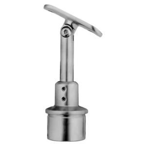
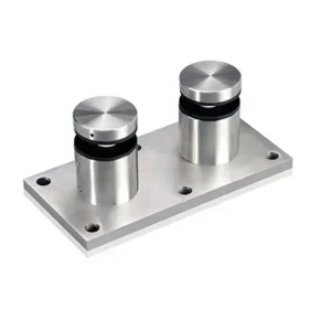
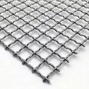
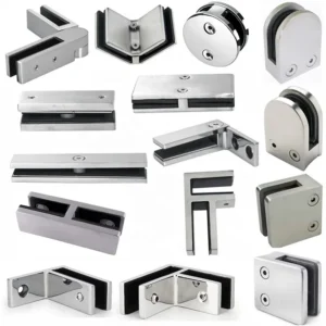
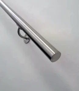
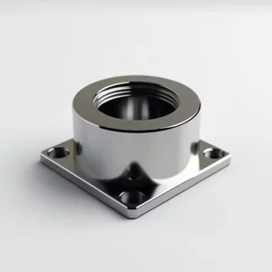
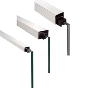
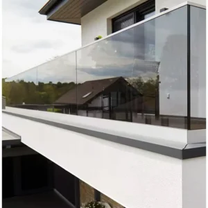
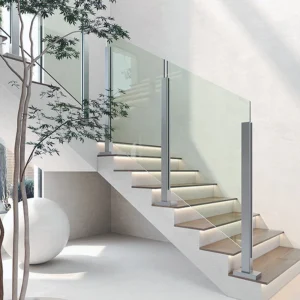
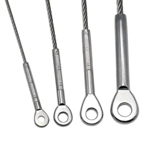
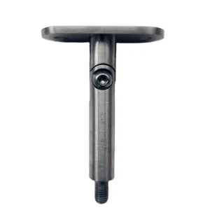
A surface-mounted handrails specification is complete when it names the function of the assembly, shows the entire rail path on drawings, and defines the structural element each mount actually lands on. “Surface-mounted” describes only how the hardware meets the supporting surface: a flange, base plate or bracket fixed to the face of a floor, stringer, wall or structural member rather than cast or core-drilled into it. What changes the specification is the function (handrail for grasping, guard for fall protection, or both), the substrate behind each fixing point, and the exposure at the mounting interface, because those three determine the loads, the anchors and the corrosion detail you must resolve before a supplier can quote.
Define the assembly function and complete rail path
Start by declaring whether the assembly is a handrail, a guard, or a combined handrail-and-guard, because that declaration sets the project criteria and the information the post, bracket and anchorage package has to satisfy. A handrail provides a continuous graspable surface for support along stairs, ramps and walkways. A guard protects an open edge against falls and carries loads applied across the infill and the top rail. A combined assembly does both, and the top member then has to work as a grasping surface and as part of a load-resisting barrier at the same time.
A product category name cannot select the governing project requirements for you. Two assemblies can both be sold as surface-mounted handrails, be built from similar tube and similar base flanges, and still face different load and deflection criteria because one guards a 1.2 m drop and the other is a wall-side grab rail on a short flight. ASTM E985-24 covers permanent building metal guardrails, stair rails, ramp rails and handrails, including basic design and load and deflection criteria, but it is written as a public standard for buildings; field-specific criteria stay with the project, and the standard excludes ballasted systems and workplace occupancies governed by occupational-safety requirements.
Alongside the function, show the actual supporting surface and structural element for every mount on the drawing. “Fixed to the floor” is not a specification. A base flange landing on a concrete slab, on a lightweight topping over metal deck, on the top of a steel stringer, or on a nosing with a limited edge distance will each change the anchor type, the plate footprint and sometimes the post spacing. Mark these on the plan and sections, and mark the ones you have not yet confirmed, so the open items are visible rather than assumed.
Take the rail path as a whole. Walk the route on the drawing from the bottom start to the top finish, through every landing, intermediate post, change of direction and termination. Where the path crosses a construction joint, a stair-to-landing transition or a change of substrate, that location is a specification decision in its own right, not a detail to leave to the installer.
Coordinate the profile, supports and mounting substrate
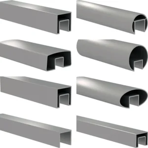
Select the profile and the support arrangement together on one drawing, because a tube section, a bracket projection and a post position are a single system from the installer’s hand outward. Define the intended grasping surface, continuity along the run, returns at the ends, transitions at landings and direction changes, and where each support sits. A convenient tube profile or an attractive post detail can still conflict with the required use of the finished rail: a wide flat-topped section may look right in elevation and be awkward to grip; a bracket mounted too close under the rail may leave too little hand clearance; a post at a landing nosing can interrupt continuity exactly where a user needs it.
Where the project falls within U.S. accessibility scope, the Access Board’s stairways guide addresses handrail continuity, gripping surfaces, clearance and extensions on covered means-of-egress stairs. Those provisions apply only where the project is covered, so confirm coverage and the adopted requirements before you fix profile dimensions, bracket projections or extension lengths from them. On projects outside that scope, continuity and grip are still design decisions you must make deliberately; they are simply governed by whatever the project does adopt.
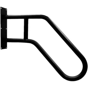
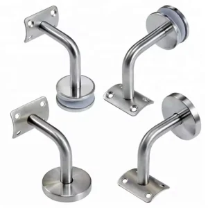
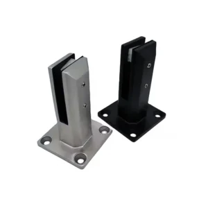
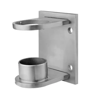
The mount is where coordination usually breaks down. Before you freeze a base plate or bracket, compare three things: the connection geometry available, the installation access, and verified information about the substrate. Connection geometry covers the plate or bracket footprint, bolt pattern, edge distances to slab edges and stair nosings, and whether a cover flange will conceal the fixings. Installation access covers whether a drill and torque tool can reach the fixing positions after adjacent work is in place, whether anything can be reached from below, and whether a side-mounted plate on a stringer or fascia is easier to install than a top-mounted one on a narrow tread.
A surface-mounted appearance covers several different structural interfaces, and the hardware has to suit the one actually present. A post base that performs on a thick concrete slab with generous edge distance is a different engineering problem on a thin topping, on timber, or bolted to the web of a steel channel. Where the substrate has not been verified by survey, record or structural drawing, treat it as an open design input and say so in the package rather than letting a proposed base detail harden into a purchase decision. The structural adequacy of the supporting element for the anchor forces is checked by the project’s responsible designer; the hardware selection follows that check, not the other way around.
Specify exposure, finish and wet interfaces
Specify material, finish, contact interfaces, drainage and surface-treatment requirements against the exposure the rail will actually see, not against a general outdoor-or-indoor label. A grade designation on its own tells you the alloy family of the parent material and nothing about the fabricated connections, the surfaces created by cutting and welding, or the places where water will sit. Those details decide how a coastal or wet-interface installation behaves over time.
The interfaces matter more than the tube. At a surface mount, the base plate sits flat on the deck, the fasteners pass through it, and the gap under the plate holds whatever runs across the surface. A crevice between plate and substrate, a weld that has not been cleaned back after fabrication, and a dissimilar metal at an anchor or shim all create conditions where stainless steel performs worse than the bare grade would suggest. So write the specification in terms of the actual details: whether base plates are set on a drainage detail or sealed, whether fixings are the same alloy family as the plate, whether shims and isolation washers are specified where a different metal is in contact, and whether the rail is drained or ventilated where it is a closed tube.
Welded and cut surfaces need their own requirement. Call out the surface treatment for field-cut ends, welded joints and any ground area, and state the finish reference for the visible surfaces so a supplier can quote the same work you have in mind. Where the rail passes a wet interface such as a pool surround, a wash-down area or a splash zone at the base of a stair, say where the water comes from, what is in it, and whether the surface is cleaned with chemicals, because the exposure at the base of a post is often harsher than the exposure on the rail above it.
No generic stainless designation guarantees a maintenance-free installation. In coastal and chloride-bearing environments, the cleaning regime is part of the specification: state the expected cleaning frequency and method as a project requirement so the owner, the specifier and the supplier are working to the same assumption about how the finish will be maintained.
Allocate design and installed-system responsibilities
Write down who is responsible for connection design, installation, inspection and project approval, because a coordinated set of components can still leave the supporting-structure checks and the field fixing work outside the supplier’s scope. A component supplier can furnish posts, rails, brackets, flanges and fittings to a drawing and can state what those parts are made from and how they go together. Whether a particular anchor into a particular slab resists the project’s design loads is a connection-design question tied to the structure, and it is answered by whoever the contract makes responsible for it.
Set the boundaries explicitly in the purchase package. Name who produces the connection details and the anchor selection, who supplies the anchors themselves, who installs, who inspects the completed installation, and who approves it for the project. Where the specification calls for load testing or other verification of the installed system, say who arranges it, who witnesses it and whose acceptance closes it out. Follow the allocation that the contract actually sets rather than assuming turnkey supply, since the same supplier scope can mean very different things on two projects.
Acceptance of the installed assembly is a project decision. Where a release or approval of the completed handrail is required, the project’s approved procedure and its designated approver decide it; a supplier’s component documentation supports that decision but does not make it. That distinction is worth stating in the package, because it determines which submittals have to arrive before the installation can be signed off.
UFGS 05 52 00 Металлические перила is useful here as an example of how a metal-railing specification and its submittal list can be structured for project-specific editing. It is a government guide specification written to be edited for a project, not a universal code and not a statement of what any supplier’s products must be, so treat it as a model for organizing your own document rather than as a requirement to import wholesale.
Issue a coordinated specification and quotation package
| Элемент упаковки | Information to show | Open condition to flag |
|---|---|---|
| Assembly function and layout | Handrail, guard or combined function; plan and sections showing the complete rail path | Function is undecided, or quantities and dimensions remain preliminary |
| Profile and supports | Intended grasping surface, continuity, returns, transitions and support arrangement on the coordinated drawing | A proposed profile or support detail has not been coordinated with the complete rail |
| Mount and substrate | Base or bracket details, actual supporting structural element, substrate information, connection geometry and installation access | Substrate conditions are unverified or the mount detail remains a proposal |
| Exposure and finish | Material and finish reference, actual exposure, contact interfaces, drainage and surface-treatment requirements | A grade label is supplied without the applicable fabricated-interface and finish details |
| Supply and installation scope | Actual allocation of connection design, installation, inspection and project approval; boundaries for supporting-structure checks and field fixing | A responsibility is unassigned or assumed to be included in component supply |
| Required submittals | Project-required submittals, including the assembly-specific load evidence and material-document checks identified for purchase | A proposal or supplied document has not been matched to the selected assembly or specified components |
Issue one package that lets every supplier quote the same scope: plan and sections showing the full rail path, the rail and post profiles, the mount details, the substrate data behind each fixing, the finish reference, and the list of required submittals. Label clearly what is confirmed and what is still a proposal, so a quotation prices the known work and flags the interfaces that must be closed before manufacture rather than burying them in an allowance.
Preliminary quantities and dimensions should stay labeled preliminary all the way through the quotation stage. A take-off from an early plan, a run length scaled before the stair is set out, or a post count based on an assumed spacing will all change, and a supplier who treats them as fixed will either carry risk in the price or raise a variation later. Marking them preliminary costs nothing and keeps the comparison between quotations honest.
The submittal list is where the package earns its keep. Decide which evidence has to come with the goods and which has to come after installation, and tie each item to the specific assembly or component it describes. Load evidence is assembly-specific: a test or calculation belongs to a particular configuration of post, spacing, base and substrate, so define the configuration first and then ask for evidence that matches it. Material documentation works the other way round, item by item: сертификаты испытаний мельниц and similar records should be requested against the specified tubes, brackets and fittings so that what arrives on site can be matched back to what was specified.
For an ESANG inquiry on surface-mount assemblies, have the following ready: the stair and landing plan with sections, the declared function of each run, the rail and post profiles with the intended grasping surface and bracket projections, the substrate and edge-distance information at every mount with the unverified locations marked, the exposure and cleaning regime, the stainless grade and finish reference, the submittal list, and the contractual split between component supply, connection design, installation and inspection. With those in hand, the quotations you receive will be comparable, and the remaining open items will be the ones that genuinely need a project decision rather than the ones nobody wrote down.
Часто задаваемые вопросы
Вопрос: Can I request quotations before the mounting substrate has been fully verified?
A: You can seek preliminary proposals, but identify the unverified substrate conditions and label preliminary dimensions and quantities clearly. Keep the base or bracket selection open until the supporting structural element, connection geometry and installation access have been checked; do not present a proposed connection as a confirmed manufacturing detail.
Вопрос: How should I compare an alternative base or bracket offered in a quotation?
A: Compare it against the same supporting surface, structural element and rail layout used for the original proposal. Check whether it changes the support arrangement, connection geometry or installation access, and identify any resulting design or field-work responsibility. A similar visible rail profile does not resolve those differences.
Вопрос: Should I use the dimensions in a U.S. accessibility guide for every project?
A: No. First establish whether the project falls within the guide’s scope and confirm the applicable project requirements. Then coordinate the gripping surface, continuity, clearances, returns and transitions as a complete rail path rather than selecting a profile from an isolated dimension.
Вопрос: Does buying a coordinated component set also cover the installed system?
A: Do not assume it does. Confirm who is responsible for connection design, supporting-structure checks, field fixing, installation, inspection and project approval. If responsibilities are split, make each boundary explicit in the purchase scope so that a component quotation is not mistaken for an offer covering the complete installation.