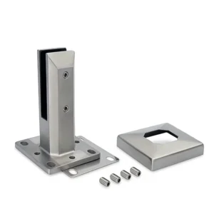
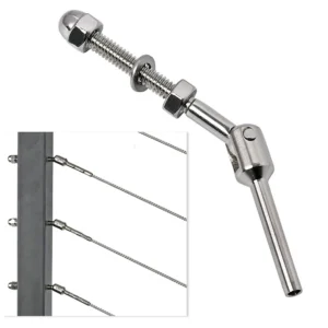
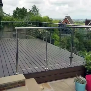
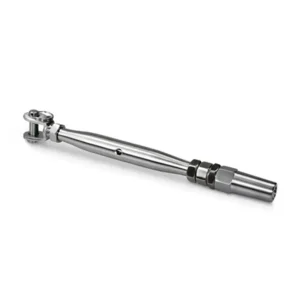
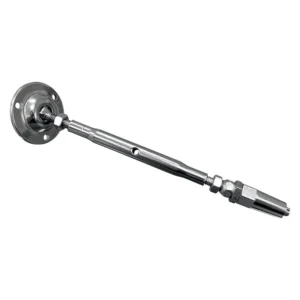
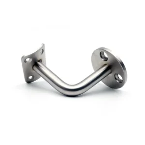
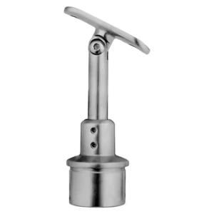
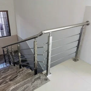
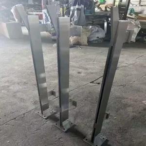
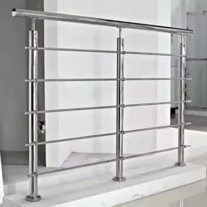
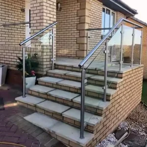
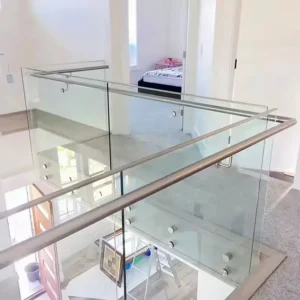
Leveling railing post base plates on a sloped substrate starts with deciding where the plumb correction will come from: adjustment built into the base assembly, shims placed under the plate, a grout bed formed under the plate, or correction of the substrate itself. The slope magnitude at each post, the bearing contact the base needs, the anchor projection left after the base sits at its final elevation, and the drainage path across the finished surface decide which of those is workable. A post base is level when the plate establishes plumb alignment for the post while still bearing on a continuous, approved surface and leaving the anchors enough engagement and projection to be fixed as detailed.
Measure Structural and Finished Slopes Separately
| Survey reference | Record at each post | Use in the leveling decision |
|---|---|---|
| Structural plane | Measured slope and local high point | Establish the substrate condition for the base-leveling route |
| Finished surface | Measured slope and local high point | Keep the finish geometry separate when checking drainage and trim-cover fit |
Survey the structural plane and the finished surface as two separate records at every post location, because their slopes and their local high points do not necessarily coincide. A concrete deck may fall in one direction for drainage while the tile, paver, or topping above it falls differently, or carries a local hump at a saddle, a drain surround, or a cold joint. If you survey only one of them, you will size a leveling detail against a plane the base plate never actually touches.
Which plane governs depends on what the plate bears on. A base plate fixed to the structural slab takes its bearing and its anchor geometry from the structural plane, and the finished surface then governs only the drainage check and the fit of any trim cover around the post. A base plate set on the finished surface takes its bearing there, and the structural plane still governs anchor embedment and the depth available below the base.
Record slope and local high point separately for each plane at each post rather than taking a single average across the run. Posts are discrete bearing points, and an averaged slope hides the one location where the plate rocks on a high spot or where the gap under the plate opens past what the selected leveling material can fill. The high point matters as much as the slope because it sets the minimum base elevation at that post, and therefore how much anchor projection remains above the plate.
Distinguish Base Adjustment From Shims, Grout, or Rework
Select the leveling method by how the chosen assembly actually obtains plumb alignment and bearing, not by what the slope measurement looks like on its own. Some base assemblies carry their own adjustment hardware; others expect shims; others expect a formed bed below the plate; and where the substrate itself is out of plane beyond what any of those can absorb, correcting the substrate is the remaining path. Each of these transfers load to the structure differently, which is why the method is a design decision rather than a field preference.
Adjustment built into the base assembly works by holding the plate at a fixed position while a secondary element sets the post’s attitude, so the load path runs through the adjusting elements and whatever material fills the space they create. Shims work by stacking bearing material in the gap, so the load path stays direct but the contact area depends entirely on how the shims are arranged. A grout bed works by filling the designated space under the plate so that bearing is continuous across the plate footprint, which is why it has preparation and thickness conditions that shims do not. Substrate correction removes the variable instead of accommodating it, and is usually the route when the out-of-plane condition is too large or too irregular for the base assembly’s intended adjustment.
Adjustment methods and their ranges belong to the specific mounting detail they were published for. Formulated Materials’ Integrated Railing System illustrates this: in that named system, a Direct Mount installation uses a plate between the post flange and the deck with leveling bolts to adjust alignment, while a Stanchion Mount installation uses shims to compensate for minor surface irregularities. The two mounting details in one proprietary system already use different adjustment mechanisms, so an adjustment method or range quoted for one detail cannot be carried across to another detail, another manufacturer’s base, or a stainless-steel post base without the governing detail saying so.
A specified grout bed fills the designated space and provides contact; it is not automatically a floor-leveling overlay. The SikaGrout-212 Product Data Sheet gives a worked example of that distinction: the published use covers base and bearing plates, post fixings, and voids, and calls for sound prepared concrete, full contact, product-specific layer limits, and protected curing, while excluding unconfined floor-leveling overlays and patch repair. That document also notes that the setup is aligned before grouting, which places plumb alignment ahead of the grouting operation rather than inside it. It is a Kenya-edition product data sheet for a cementitious grout, so local product data, the project detail, and metal compatibility with stainless-steel hardware govern what material actually goes under a given base plate.
The practical rule is that a grout bed solves a bearing problem under a plate, not a flatness problem across a floor. If the slope you measured runs across the whole walking surface rather than just under the plates, you are looking at a surface question for the project team, not a base-plate detail.
Check Contact, Anchor Projection, and Cover Fit
Once you have a candidate base elevation at each post, check it against three physical conditions at the same time: continuous bearing contact under the plate, usable anchor projection above it, and clearance for whatever trim cover closes the base. These conditions move together, because raising the base to gain contact on a sloped substrate reduces the thread or stud length left above the plate and changes how far the cover has to reach down to the finished surface.
Bearing contact is the condition that decides whether the base behaves as a base plate at all. A plate resting on two high points transfers guard loads through those points rather than across the plate footprint, and it will move under lateral load regardless of how tight the anchors feel. Whatever sits under the plate — shim material, a formed bed, or direct contact on the substrate — has to be the material the project approved for that position, because its stiffness and durability are part of the load path and, at coastal or wet exterior locations, part of the corrosion picture around stainless-steel hardware.
Anchor projection is set by the base elevation, the plate thickness, any shim or bed thickness, and the embedment the anchor detail requires. On a sloping substrate the downslope side of the plate sits further from the substrate than the upslope side, so the anchor at the low corner is the one to check first: it is where the free length above the substrate is greatest and the remaining projection above the plate is smallest. If the detail uses cast-in or post-installed anchors with fixed projection, the leveling thickness you can add is bounded by that geometry before any other consideration.
Trim-cover fit is the check people leave until last and then fix with a larger cover. A cover that was drawn for a plate sitting flush on a level surface will show a wedge-shaped gap when the same plate is leveled on a fall, and on an exterior deck that gap is also a water path into the base. Decide early whether the cover follows the plate, follows the finished surface, or needs a detail that accepts a variable gap, and confirm that the plate position you have chosen leaves the cover room to seat.
Preserve Drainage While Establishing the Post Datum
Establishing a shared post datum gives every post the same vertical and alignment reference, but it must not flatten out the fall the finished surface needs to drain. The datum sets where the tops of posts and the rail line sit; the finished surface keeps its own slope underneath. Problems appear when the leveling material used to reach the datum spreads beyond the plate footprint and forms a low dam across the fall, or when a plate is raised in a way that creates a pond on its upslope side.
Keep the two geometries distinct in the detail. The datum is a line you set and hold for alignment; the drainage condition is a property of the finished surface that the base detail has to leave intact. A leveling material confined under the plate, within the plate footprint and whatever edge the detail allows, generally preserves the surrounding fall. A leveling material that feathers out across the deck is behaving as a floor overlay, which is a different scope with different preparation and thickness conditions, and in the SikaGrout-212 example is explicitly outside the product’s stated use.
On exterior and coastal work the drainage check is also a durability check. Standing water held against a stainless-steel base plate, in the joint between the plate and the material below it, or inside a trim cover, keeps chlorides in contact with the metal and the fixings far longer than a surface that drains. Where you cannot avoid a local flat spot at a post, the detail — not the installer on the day — should say how that water leaves.
Document the Selected Leveling Materials and Installation Limits
| Record item | Project-specific entry | Decisão apoiada |
|---|---|---|
| Adjustment source | Adjustment built into the selected base, or project-provided shims, grout, or substrate correction | Identifies the selected leveling route before anchor geometry is fixed |
| Interface material | Approved material below the base plate | Provides the material basis for the bearing-contact check |
| Installation limits | Project-defined limits for the selected route | Sets the boundary for applying the selected detail |
| Anchor geometry | Geometry coordinated with the selected leveling route | Connects the base-elevation choice to the anchor-projection check |
| Post datum and tolerance plan | Shared post datum and recorded tolerance plan | Provides the common reference for later alignment acceptance |
Record the leveling detail you will build before anchors are set, because the base elevation chosen at each post fixes the anchor geometry and cannot be revisited cheaply afterward. The record is short and specific: where the plumb adjustment comes from, what material sits under the plate, the installation limits that apply to that material or assembly, the anchor geometry coordinated with the chosen base elevation, and the shared post datum and tolerance plan the installed posts will be checked against.
Each entry exists because something downstream depends on it. Naming the adjustment source prevents an adjustment range published for one mounting detail being applied to a different one. Naming the approved material below the plate gives the bearing-contact check something definite to be assessed against, and keeps metal compatibility with stainless-steel hardware in view on exterior and coastal projects. Recording the installation limits — preparation condition, thickness, curing protection, or the usable adjustment range of the base assembly — marks the boundary beyond which the detail no longer applies and the condition has to go back to the designer.
The material-specific limits come from the local product data for the actual material used and from the project detail, not from a published example of a similar product. A data sheet issued for one country’s formulation, or a leveling component published for a named aluminum railing system, shows what the conditions look like; it does not set them for a stainless-steel base plate on your deck.
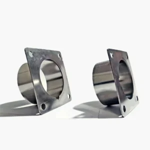
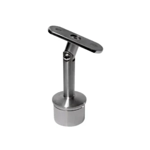
For the supplier discussion that follows this record, have the base-plate drawing with its bolt pattern and plate thickness, the measured structural and finished slopes and high points at each post, the substrate type and available embedment depth, the anchor type and projection, the exposure and specified stainless-steel grade and finish, and the trim-cover detail. With those in hand, the choice between an adjustable base plate and a placa de base para montagem em superfície becomes a geometry question with a defensible answer rather than a field improvisation. ESANG supplies both types of post hardware, and which one suits a sloped substrate depends on the adjustment the detail needs and the anchor geometry it leaves behind.
Accept the Base Detail Against the Project Tolerance Plan
| Acceptance check | Evidências a serem comparadas | Project-specific boundary |
|---|---|---|
| Alinhamento de postes | Installed post position against the shared datum | Apply the recorded tolerance plan rather than treating every uneven location as the same condition |
| Bearing contact | Base-plate contact with the approved material below it | Accept against the selected leveling detail and its installation limits |
| Anchor projection | Anchor projection at the selected base elevation | Confirm compatibility with the anchor geometry established for the selected route |
| Drenagem | Drainage condition at the finished surface after the datum is established | Confirm that the selected leveling detail preserves the project drainage condition |
| Trim-cover fit | Cover fit at the leveled base and finished surface | Confirm fit against the selected base position and local finish condition |
Acceptance of a leveled base is a comparison between what was installed and the recorded tolerance plan for that project, not a judgment made post by post in the field. A shared post datum and a written tolerance plan let you check alignment against one reference and identify the locations that genuinely fall outside it, instead of treating every uneven spot as an equal problem or, conversely, accepting a drifting line because each post looked acceptable next to its neighbor.
The checks at acceptance are the same conditions that drove the detail: post alignment against the datum, continuous bearing contact on the approved material below the plate, anchor projection consistent with the geometry established for the chosen base elevation, drainage at the finished surface after the datum has been set, and trim-cover fit at the leveled base. Each is compared with its own project-specific boundary. A post within the tolerance plan but bearing on two high points has not passed; a plate with full contact but insufficient anchor projection has not passed either.
ASTM E985-24, Permanent Metal Railing Systems and Rails for Buildings, is the standard whose public scope covers permanent metal building railings and basic load and deflection criteria, with its stated exclusions for ballasted railings and certain adult-only occupational-safety applications. The field-specific design criteria for a particular guard — the loads it must carry, the deflection allowed, and the acceptance limits applied to the installed base — remain with the designer, the specification writer, and the code agency for the project. Where the measured condition at a base falls outside the recorded tolerance plan, the decision to accept the base as built, to rework it, or to adopt an alternative leveling detail belongs to the project’s approved procedure and its designated approver, who hold the design basis the acceptance limits come from.
What the installer can settle on site is the evidence: the as-built position of each post against the shared datum, the material and thickness actually placed under each plate, the projection left at each anchor, and photographs or measurements at the locations that differ from the typical detail. That record is what turns a disputed base into a decision someone can make.
Perguntas frequentes
P: Can the same leveling detail be used for every post along a sloped run?
A: Only where the measured conditions fall within the documented limits for that detail. Keep one shared post datum, but compare the structural slope, finished-surface slope, and local high point at each post before grouping locations under the same leveling route.
P: Can shims or grout be treated as interchangeable with adjustment built into the base?
A: No. Identify whether adjustment comes from the selected base, project-provided shims or grout, or substrate correction, and record the approved material and installation limits for that route before setting the anchor geometry.
P: When should the anchor geometry be finalized?
A: Finalize it after the leveling route and resulting base elevation have been selected. Then check the required anchor projection together with bearing contact, finished-surface geometry, and trim-cover fit at that elevation.
P: What should the installer do when a post location falls outside the selected detail’s limits?
A: Do not improvise the same detail at that location. Record the structural and finished-surface measurements, then resolve whether another approved leveling route or substrate correction is required before fixing the anchors.
P: Does a well-fitting trim cover confirm that the leveled base is acceptable?
A: No. Treat cover fit as one separate check; also verify base-plate contact with the approved interface material, anchor projection, drainage at the finished surface, and post alignment against the shared datum and tolerance plan.