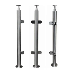
Through-post cable hardware is the group of terminals, tensioning parts, guides, washers and finishing pieces used where a cable line meets or passes through a railing post. It is not one universal connector. A useful enquiry starts by identifying whether each post is a fixed end, an intermediate guide, a corner or a tensioning end, then matching the hardware to the post, cable and installation access.
Discuss through-post cable hardware on WhatsApp
Begin with the role of every post
A terminal post and an intermediate post may have holes on the same cable line, but the hardware at those holes performs a different job. The terminal transfers cable force into a bearing surface and the post frame. The intermediate fitting mainly guides the cable through the post and protects the cable from the drilled edge. A corner must either terminate separate runs or use a corner route that has been confirmed for the selected cable and hardware. The opposite terminal normally provides the planned tension adjustment.

- Fixed terminal post: requires a termination matched to the cable and a post face or internal reinforcement able to receive the terminal load.
- Intermediate post: requires a clean, aligned pass-through detail; it should not be specified as the cable anchor unless a separate terminal system is deliberately designed there.
- Corner post: needs a layout decision before hole drilling. Treating it as an ordinary intermediate post can bend the cable against a sharp edge or combine loads that the post detail was not prepared to receive.
- Tensioning terminal post: needs the selected adjustment mechanism plus enough rear-side clearance for installation, trimming and future adjustment.
Match the terminal to the post interface
Through-post hardware is controlled by more than the visible fitting. Send the post profile and outside size, wall thickness or solid-post depth, hole diameter, hole centreline, cable direction and the accessible side of the post. For a hollow round or square post, the usable bearing face, internal clearance and any reinforcement matter. For a solid post, the drilling depth and the route available for a through-bolt or face-mounted alternative can change the solution.

Washers, shaped seats or load-spreading plates must sit against an appropriate bearing surface. A washer intended for a flat face may not seat correctly on a curved post. A fitting that spans a thin wall differently from the intended design may crush or distort the post face; a short thread may not fully engage, while an overlong body may conflict with another cable row or the opposite post wall. These details should be settled before posts are drilled or fabricated.
Choose a fixed end and a tensioning end as a pair
Each cable run needs a defined fixed end and a defined means of tension adjustment. The adjustment may be at one end or distributed according to the selected system, but it should not be assumed from the fitting’s appearance. Ask ESANG to identify the function of every proposed end component, its cable attachment method, adjustment direction, available take-up, required tool access and finished exposed profile.
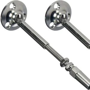
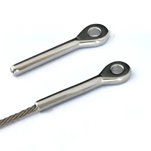
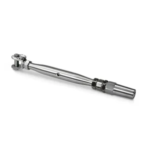
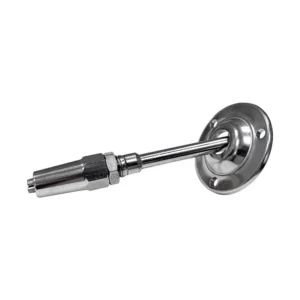
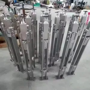
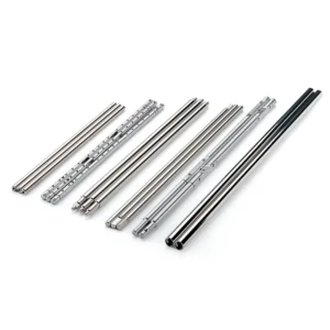
The current ESANG product image below shows long tubular end components, an exposed threaded section, an Allen key and small installation examples. It supports a discussion about interface length and tool access, but the image alone does not establish an internal cable-gripping method, thread size, material, load rating or a complete supply package.

Cable diameter is only the first compatibility field
Give both the nominal cable diameter and the cable construction. Cable with a different strand construction can have a different outside behaviour, stiffness and response to cutting, swaging or mechanical gripping even when the nominal diameter appears similar. Also state whether the cable will arrive as bulk reel, factory-ended assembly or field-finished length.
The terminal must be approved for that exact cable input and termination process. Do not combine a cable, fixed terminal and tension terminal from different sources merely because the visible diameters look close. A mismatch can allow the cable to slip, prevent full insertion, damage strands, seize during adjustment or leave too little take-up after field cutting.

Plan straight runs, stairs and corners separately
Straight level runs
Keep the fixed end, intermediate holes and tensioning end on the intended cable axis. Record the hole heights from one controlled datum and identify whether the post arrives pre-drilled or will be drilled on site. The required hole size changes with the selected cable, terminal body, sleeve or bushing; it must come from the confirmed hardware schedule rather than from a generic hole chart.
Stair runs
A stair cable approaches the post at an angle. The hole axis, fitting seat and any angled washer must follow the approved stair pitch so the cable is not forced across a sharp entry edge. Send the rise/run or measured cable angle, the post orientation and a side elevation. Also show whether the stair terminal is at the upper or lower end, because installation access and the exposed fitting direction may differ.
Corner runs
Do not assume cable can be pulled around a corner post. A corner may use separate terminated spans, a double-post arrangement or a specifically confirmed continuous-routing detail. The decision affects the number of fixed and tensioning ends, the drilling pattern, local bearing faces and access. Include a plan view with the corner angle and identify whether independent span adjustment is required.
Decide what is factory prepared and what happens on site
Field work may include post layout, drilling, deburring, inserting guides, measuring cable, cutting, terminating, tightening and final adjustment. The actual tool list depends on the agreed hardware and cable. Typical planning fields include:
- a drilling jig and bits suitable for the post material and confirmed hole sizes;
- deburring and edge-cleaning tools so cable does not bear on a sharp hole;
- cable cutters suitable for the selected cable construction;
- holding and wrench tools for the specific terminal flats and nuts;
- a swaging tool only when the selected terminal actually uses a field-swaged connection;
- the system’s specified method for checking and sequencing cable adjustment.
Ask the response to distinguish factory machining and assembly from installer work. If posts are supplied by another party, exchange an approved hole schedule before fabrication. If cables are cut in the field, allow for insertion depth and adjustment reserve; cutting a line to the visible clear span alone can make the terminal impossible to assemble or adjust.
Definir o limite de abastecimento
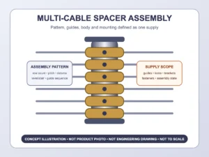
A through-post hardware enquiry may concern individual fittings, a matched cable-and-end package, or a wider railing assembly. State the boundary you need. ESANG’s response should list the proposed components and quantities rather than relying on the phrase “complete system.” For each cable line, that list may need to address:
- cable type, construction, diameter and supplied length basis;
- fixed-end terminal and cable attachment method;
- tensioning terminal and adjustment access;
- intermediate sleeves, grommets or pass-through guides;
- corner hardware and routing method, where applicable;
- washers, shaped seats, nuts, caps and other visible finishing pieces;
- posts or post machining, if requested;
- special installation tools or replaceable tools, if they are part of the proposed supply;
- items by others, including post reinforcement, bases, anchors, top rail, substrate work and final site adjustment unless explicitly included.

What to send for an actionable enquiry
You can start with a marked photo, sketch and estimated quantity. Before an order is frozen, provide:
- plan and elevation showing every cable run, post role, corner and stair transition;
- post material, shape, outside size, wall thickness or solid depth, and rear-side access;
- hole schedule if already designed, or confirmation that ESANG is being asked to propose the interface;
- cable nominal diameter, construction, source and required length basis;
- fixed-end and tensioning-end preference, including acceptable exposed hardware;
- environment and finish request for confirmation, without assuming a material from a photograph;
- factory-machined versus site-machined boundary and installer tool capability;
- quantity by component and any packaging or replacement-piece requirement.
The proposed supply should return a component schedule, cable/terminal pairing, post-interface requirements, field operations, included tools or accessories, exclusions and any information still needed for final confirmation. That is the comparison basis for two offers; a shared product name is not enough.