Freezing glass panel dimensions before confirming the actual opening geometry and fixing substrate is the single most common error in Juliet balcony projects — and by the time it surfaces, waterproofing layers are often already in place. The cost is not just a remeasurement; it is removing sealant, repositioning brackets, and potentially reordering glass to a corrected size. Door swing, drainage position, and wall substrate type all interact with that initial geometry decision in ways that are difficult to undo once the opening is committed. Working through the sequence below will sharpen the checks that need to happen before hardware selection is finalised, not after.
Opening geometry that governs Juliet glass support
The first confirmed measurement is not the glass size — it is the clear opening width, because everything else derives from it. Facade construction tolerances are rarely as consistent as drawings suggest, and a panel dimension that reads correctly on a CAD file can be wrong by enough to require a reorder once the opening is built. Before any glass is sized, the actual opening should be physically verified on site rather than taken from documentation.
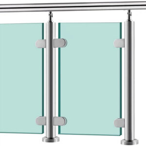
Span capacity governs whether a single panel or multiple panels are needed. At widths approaching 4100 mm, a continuous glass run without intermediate support reaches the practical limit of what most systems can span — beyond that threshold, intermediate posts or additional support brackets become structurally necessary. That 4100 mm figure should be treated as a design threshold specific to the system under review, not as a universal regulatory maximum across all jurisdictions or hardware types. The structural implications shift meaningfully on either side of it: below that span, a clean uninterrupted glass elevation is typically achievable; at or beyond it, the visual and structural logic of the installation changes.
What this means practically is that opening width must be confirmed and signed off before any supplier is asked to quote panel sizes. Fabrication lead times for structural glass are long enough that an incorrect dimension locks a project into a costly path. A substrate check — confirming the fixing material directly, not inferring it from drawings — belongs in the same confirmation sequence, because wall capacity governs hardware selection just as much as span does.
Door and drainage conflicts that alter bracket planning
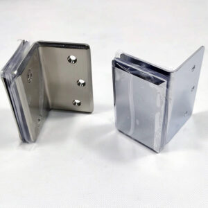
Door configuration is a planning input that must be resolved before bracket positions are set, not after. An inward-swinging single door, an inward-swinging French door, and a sliding door each present a different spatial envelope at the threshold, and bracket types that suit one configuration can physically interfere with another. When that mismatch is caught late — after waterproofing is applied and penetrations are made — the remediation cost is substantially higher than a configuration review would have been during design.
The drainage condition at the threshold compounds this. On projects where a drainage channel runs close to the opening sill, bracket positions that seemed straightforward on drawings may land directly over a drainage element, creating a conflict that forces a choice between compromising the drainage path or relocating the bracket. Relocating the bracket after the fact often means a new penetration through the facade membrane — exactly the scenario the waterproofing section of any specification is trying to prevent.
The productive approach is to treat door type and drainage layout as co-inputs at the same stage as opening geometry confirmation. Specifying which door configuration is present and where drainage elements sit relative to the threshold should happen before any bracket layout is drawn. Projects that skip this step tend to discover the conflict during installation, when the schedule pressure to proceed makes a careful redesign unlikely and a compromised detail more probable.
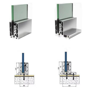
Face fixed hardware choices versus floor edge details
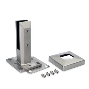
For projecting Juliet balconies, both deck mount and fascia mount options are structurally viable, and the selection carries real consequences for installation sequence, anchor zone preparation, and visible hardware bulk. For flush balconies — those sitting in-plane with the facade — fascia mount is the only compatible option, and that constraint should be established early enough to influence facade preparation, not discovered during hardware ordering.
| Balcony Projection Type | Compatible Mounting Methods | Key Installation Consideration |
|---|---|---|
| Projecting (cantilevered) Juliet balcony | Deck mount (floor edge) or Fascia mount (face fixed) | Deck mount: floor edge attachment. Fascia mount: preserves opening, requires cleaner anchor zones and more exact measurement. |
| Flush (in-plane with facade) Juliet balcony | Fascia mount (face fixed) only | Fascia mount: preserves opening, requires cleaner anchor zones and more exact measurement. |
The practical risk with fascia mount details is that they require cleaner anchor zones and tighter measurement tolerances than deck mount configurations. Face-fixed connections preserve the clear opening and avoid projection constraints, but the wall surface behind the bracket must be flat, structurally sound, and free of voids or inconsistencies that would compromise the anchor. On site, that condition is less common than drawings imply. Deck mount details are somewhat more tolerant of minor surface variation at the floor edge, but they introduce their own constraints: the floor construction must support the load path, and the hardware footprint is more visible.
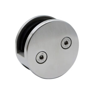
Where installers run into difficulty is in assuming that face-fixed hardware can compensate for an unprepared anchor zone through tighter fastener specification. It typically cannot. The consequence of inadequate anchor preparation with fascia mount hardware is not always an immediate failure — it is often a gradual loosening that only becomes apparent under load or after thermal cycling has worked the fasteners. Confirming glass panel support brackets are matched to a verified substrate condition, not to a drawing assumption, is the check most often skipped under schedule pressure.
Waterproofing failures around penetrations
Every bracket penetration through a facade membrane introduces a potential moisture path, and the critical question is not whether sealant is applied — it is whether the base detail was resolved before the penetration was made. Sealant applied after the fact to a poorly sequenced penetration is managing a risk rather than eliminating one. Moisture tracking behind a facade membrane, rather than appearing at the penetration itself, is the failure mode that goes undetected longest and causes the most structural damage by the time it surfaces.
The pattern that creates long-term problems is this: waterproofing is applied to the facade, penetrations are made for brackets, and sealant is applied around the exposed hardware. If the penetration was not coordinated with the membrane installation — meaning the membrane was not lapped or detailed around the penetration opening before the bracket went in — then the sealant is the only barrier. Sealant alone ages, debonds under UV and thermal movement, and may not fully fill the geometry of a complex bracket profile. When it fails, water reaches the substrate behind the membrane, and the damage path runs downward and inward along the wall construction.
Getting the sequence right means that bracket positions are determined and penetration locations are marked before the membrane layer is installed, so the waterproofing trade can detail around each penetration as part of their normal scope. This requires bracket layout to be confirmed during design and communicated to the waterproofing installer as a coordinate, not added afterward. Projects where the railing contractor arrives after the facade is complete are structurally set up for a remedial sealant approach — and that should be treated as a risk to manage, not an acceptable standard practice.
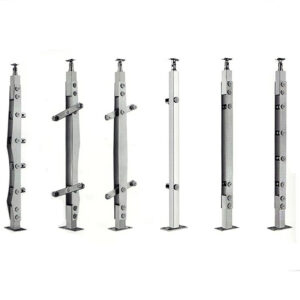
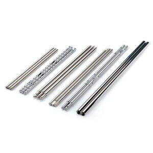
Wall capacity required for slim Juliet hardware
Slim Juliet hardware creates a specific mismatch risk: its low visual profile suggests it imposes minimal load on the structure, but the actual forces transmitted into the wall under lateral loading — particularly when the installation is tested to railing system performance expectations — are concentrated at a small number of fixings rather than distributed across a wider base. That concentration means wall capacity at each anchor point matters more, not less, than it would with a heavier-profile system spread across a larger footprint.
ASTM E985-24 provides a useful framework for understanding the performance expectations that railing systems are designed to meet. The standard addresses the structural behavior of permanent metal railing systems under load conditions relevant to buildings, and reviewing it helps establish what the fixing substrate needs to resist — even if the specific span or load figures for a given installation are governed by the applicable local standard or the system manufacturer’s engineering documentation.
Wall substrate type determines whether those performance expectations can be met at all, and the substrates most commonly encountered in Juliet installations — rendered masonry, insulated composite panels, timber-framed construction with cladding — vary significantly in their capacity to resist the pull-out and shear loads that slim brackets impose. Confirming substrate type from a physical investigation, not from a building specification document that may not reflect as-built conditions, is a necessary step before hardware selection is finalised. Where capacity is marginal, using a different fixing pattern, a backing plate, or a through-bolt detail may resolve the issue — but those decisions need to happen during design, not during installation when the alternative is an undersized anchor in a completed facade.
The mistake pattern to avoid is selecting hardware based on visual fit to the project aesthetic and then treating the structural confirmation as a formality. On slim Juliet systems, that sequence inverts the risk logic. Hardware selected for its profile should be treated as a candidate until substrate capacity is verified, not as the confirmed solution.
The decisions that govern a Juliet balcony installation converge in a narrow window before the opening is committed and the facade is closed. Opening geometry, door configuration, drainage position, bracket type, and substrate capacity all need to be resolved as a coordinated set — not as sequential choices made by separate trades without a common reference. Glass sizing, hardware selection, and waterproofing sequencing each depend on what the others have confirmed.
For anyone specifying or procuring this system, the practical next step is to define what is already confirmed versus what is still assumed. Any assumption still in the stack — whether about wall substrate, door swing clearance, or facade surface flatness — should be treated as a risk that may require a design revision to resolve. Confirming those points before hardware is ordered is substantially cheaper than addressing them after the membrane is applied and the glass is cut.
Perguntas frequentes
Q: What happens if the wall substrate turns out to be a composite insulated panel rather than solid masonry — can slim Juliet hardware still be used?
A: It depends on whether the panel’s pull-out and shear capacity at each fixing point meets the load requirements for the specific bracket system, which cannot be assumed without manufacturer data for that panel type. Composite insulated panels vary widely in their structural core, and the concentrating effect of slim Juliet hardware means marginal substrates fail at fewer fixings with less warning. A backing plate or through-bolt detail may restore viability, but that determination belongs in the design phase, not on installation day.
Q: Once opening geometry, substrate, and bracket type are all confirmed, what is the immediate next step before ordering glass?
A: The confirmed measurements and bracket positions should be communicated to the waterproofing installer as marked coordinates before the membrane layer is applied. Glass fabrication lead times mean the order will likely be placed while facade work is still in progress — so the sequencing risk is that brackets get treated as a railing trade responsibility arriving after the facade is closed. Handing penetration locations to the waterproofing contractor as a documented input, not a verbal note, is the action that prevents the remedial sealant scenario the article identifies as the most common long-term failure path.
Q: Does the 4100 mm clear span threshold apply to both projecting and flush Juliet configurations, or only one?
A: The 4100 mm figure applies to the glass span itself regardless of whether the balcony projects or sits flush, but the structural logic that follows differs between the two configurations. A projecting balcony has the option of deck mount hardware that can distribute load across a wider base, which may affect how intermediate support is detailed near the threshold. A flush balcony is limited to fascia mount only, so any intermediate support at or beyond that span must be resolved entirely through face-fixed hardware into the facade — making substrate capacity at those additional anchor points more critical than in the projecting case.
Q: Is face-fixed fascia mount hardware worth the tighter preparation requirements compared to deck mount, or does deck mount offer a more reliable installation outcome?
A: Face-fixed fascia mount is the better choice when preserving the clear opening and avoiding projection constraints matters to the design, but it only delivers that outcome reliably when the anchor zone is genuinely flat, structurally sound, and free of voids — a condition that requires physical verification, not drawing confidence. Deck mount is more tolerant of minor surface variation and may suit projects where facade preparation cannot be controlled tightly, but it introduces visible hardware at the floor edge and requires the floor construction to carry the load path. The deciding factor is not which option is inherently safer — it is which option the actual site conditions support.
Q: At what point does a Juliet guard project become too structurally complex for standard off-the-shelf hardware, and custom engineering is needed instead?
A: Standard hardware reaches its limits when two or more constraint conditions stack — for example, a span approaching 4100 mm combined with a marginal substrate and a fascia-only mounting requirement. Any single constraint can usually be resolved through hardware selection or fixing pattern adjustment. When opening width demands intermediate support, the wall cannot take concentrated loads at standard fixing centres, and the facade configuration rules out deck mount, the load path cannot be satisfied without engineering the fixing arrangement specifically for that wall. That threshold is not defined by a single measurement; it is reached when the standard product’s anchor assumptions no longer match what the site can actually deliver.