Switching tube profile after hardware samples have been submitted is one of the more expensive specification errors in a railing procurement cycle. Brackets sourced for a 1.5″ round tube will not seat a 40×40mm square profile, end caps become scrap, and polishing direction decisions made for a curved continuous run may be incompatible with the flat-face geometry of square tube connectors. The cost is not limited to replacement parts — it often includes drawing revisions, resampling lead time, and in project-schedule terms, a procurement gap that compresses installation float. The practical resolution is treating tube profile, hardware geometry, finish type, and mounting method as a single interlocked decision cluster that must close before any component is approved for order. What follows gives procurement teams, specifiers, and railing contractors the dimensional thresholds, compatibility checks, and friction points needed to make that cluster close at the right stage.
Tube shape effects on grip, appearance, and fabrication
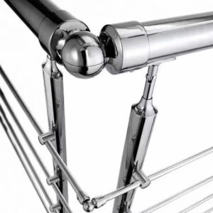
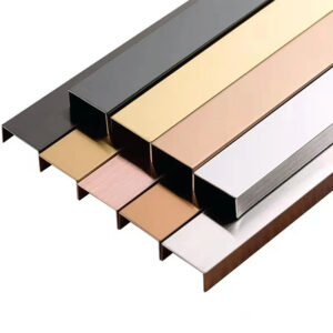
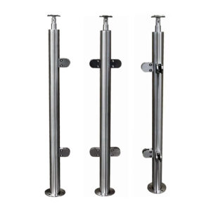
Profile shape determines more than visual language — it controls how a hand contacts the rail under load, how brackets seat and transfer force to the wall, and how fabrication tolerances interact with connector geometry. Round and square tubes are not interchangeable expressions of the same underlying component; they are different design objects that require matched hardware ecosystems from the beginning of specification.
Grip performance varies between profiles in ways that matter when surface texture is part of the specification. On round tube, textured surface conditions improve kinetic friction significantly compared to plain-finished tube — and the effect is more pronounced at smaller diameters. A 1.25″ OD textured round tube shows a dramatically larger friction increase over plain than a 1.5″ OD textured tube does over its plain equivalent, which has implications for which diameter to specify when grip security is a priority alongside code compliance.
| Diameter | Surface Condition | Kinetic Friction Increase (vs Plain) |
|---|---|---|
| 1.5 in | Textured | 1.5× |
| 1.5 in | Plain (smooth) | 1.0× (baseline) |
| 1.25 in | Textured | 6× |
| 1.25 in | Plain (smooth) | 1.0× (baseline) |
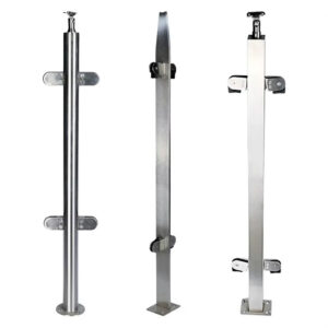
Square tube offers a different grip character: the flat faces provide a more definitive edge reference for fingers, but continuous palm contact across the cross-section is different from what round profiles allow. For runs where graspability over a full stair flight matters — particularly where ADA-adjacent guidance shapes the specification — round profiles handle that functional demand more directly. Square profiles tend to serve architectural expression better than ergonomic grip, which means the choice should be explicit in the specification rather than left to installer preference.
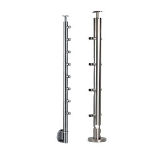
From a fabrication standpoint, round tube in standard wall thicknesses (0.060″, 0.079″, 0.102″ are common gauges) and lengths up to 22 ft allows BOM planning with relatively predictable cut yield and connector spacing. Square tube introduces corner geometry that affects how elbows and inline connectors align — and where any tolerance variance in wall straightness can affect connector seating in ways that round tube fabrication typically manages more easily. Neither profile is inherently more difficult to work with, but fabrication assumptions built around one do not transfer to the other.
Round profile advantages for code-sensitive handrail runs
The ADA gripping surface guidance constrains handrail diameter to a range of 1.25″ to 1.5″, and that range maps directly onto standard round tube OD without requiring custom sizing. A 1.5″ OD round tube satisfies the upper bound of that range; a 1.25″ OD satisfies the lower bound. Square tube, by contrast, does not present a circular gripping perimeter, which means it may require a graspable profile analysis or a specific corner radius treatment to satisfy graspability intent depending on the authority having jurisdiction. Specifying a round profile removes that interpretive layer from the compliance conversation.
Wall clearance and projection add a second dimensional constraint that is worth confirming against local code before fabrication — not after. A 1.5″ tube with 1.5″ of clearance from the wall face achieves a total projection of 3″, which is a common design checkpoint for graspability compliance. That relationship between tube OD and wall offset is set by the bracket standoff dimension, which means bracket selection and tube diameter must be confirmed together, not sequentially.
| Criterion | Code Requirement | Typical 1.5 in Round Tube |
|---|---|---|
| Gripping surface diameter | 1.25–1.5 in | 1.5 in OD meets requirement |
| Wall clearance / projection | 1.5 in wall clearance (3 in total projection) | 1.5 in tube with 1.5 in clearance achieves compliant projection |
The practical risk is not that teams are unaware of the diameter range — it is that the clearance dimension gets treated as an installation detail rather than a specification input. If a bracket is sampled based on aesthetic fit and its standoff does not achieve the required projection, the bracket must be replaced before the tube is installed. Catching that mismatch after bracket samples are approved costs a reorder cycle; catching it at the specification stage costs a conversation. Dimensional compatibility between ISO 1127-toleranced tube OD and bracket throat geometry is the verification point that prevents the reorder.
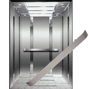
For continuous wall handrail runs where the same bracket repeats across a full stair flight or corridor, the round profile also simplifies spacing calculations because connector and end return geometry is well-standardized. Teams sourcing for those applications can reference Esang’s continuous wall handrail systems to confirm how bracket spacing and tube OD interact across standard run lengths.
Square profile tradeoffs in modern architectural projects
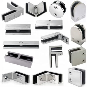
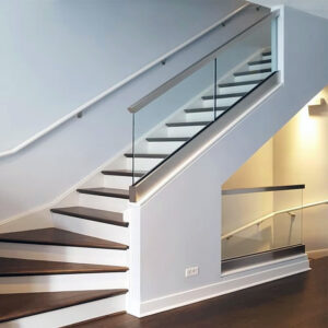
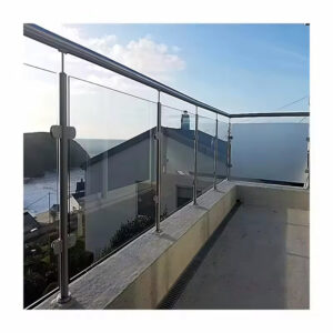
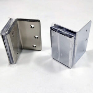
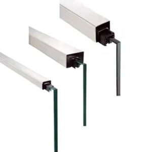
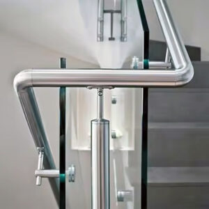
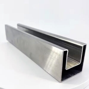
Square tube is frequently specified because it reads as architecturally current — the flat faces align with frameless glass panel lines, resolve cleanly against rectangular structural elements, and complement modern minimalist interiors where round profiles can feel mismatched. That visual logic is legitimate. The procurement consequence of acting on it without matching the hardware specification is not.
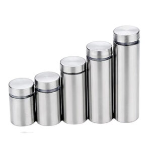
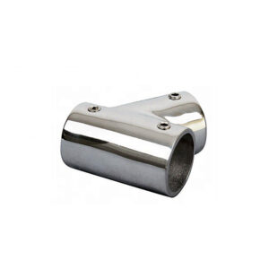
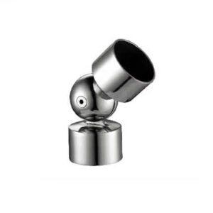
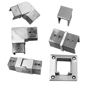
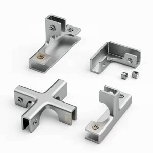
The hardware ecosystem for square tube carries different geometry than round tube equivalents, and availability across that ecosystem is not always equivalent. Brackets for square tube must accommodate flat-face seating rather than a circular bore, which affects throat design and setback geometry. Inline connectors must account for corner alignment, not just OD match. End caps for square profiles have an internal fit tolerance tied to both face dimension and wall thickness — a cap sourced from a different hardware line than the tube may show a visible gap at the face or may not seat securely at all. These are not rare edge cases; they are routine procurement outcomes when hardware is sourced after tube selection rather than alongside it.
The geometry constraint becomes more specific at transitions. Where a square tube run meets a return, elbow, or wall plate, the connector must be designed for the specific tube face dimension and corner radius. A 40×40mm square tube with a 2mm corner radius is not dimensionally equivalent to a 40×40mm tube with a 4mm radius for the purposes of connector seating, even if both describe the same nominal profile. Specifying tube profile without specifying corner radius and matching that to connector geometry is a common source of field fit problems that do not surface until the hardware arrives on site.
For teams evaluating square profile options, Esang’s square tube handrail systems include matched hardware selections that close the geometry dependency at the specification stage rather than leaving it to field resolution.
Bending radius and finish durability limits before design freeze
For runs with curved transitions — at landings, wrapped stairwells, or radius walls — tube profile interacts with bending method in ways that must be resolved before the design is frozen. Round tube bends more predictably across its cross-section because wall thinning and ovality are distributed symmetrically. Square tube bending introduces corner-specific stress concentration and face-profile distortion that becomes visible at tighter radii. Both profiles have bending limits beyond which surface integrity or dimensional accuracy is compromised, but those limits are not the same, and they are not interchangeable in curved run specifications. Full detail on radius requirements and tolerance planning for curved runs is covered in Pipe Bending Tolerances and Radius Requirements for Curved Stainless Steel Handrails.
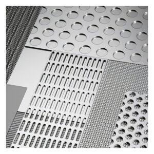
Finish selection adds a parallel design freeze constraint. Textured finishes — brushed, bead-blasted, or embossed — tend to conceal field damage more effectively than plain or mirror-polished tube because surface scratches and minor dents become visually absorbed by the existing texture pattern. For projects where rail contact frequency is high or where the installation environment involves construction traffic before handover, that practical durability difference can affect long-term maintenance cost in a meaningful way. The decision framing here is not that textured tube performs better in a tested or rated sense — it is that specifying texture versus plain finish before design freeze affects polishing direction, surface preparation requirements, and how bracket seating and connector interfaces are prepped, none of which can be easily reversed after fabrication begins. The NAAMM Metal Finishes Manual provides a useful classification framework for evaluating finish categories and their appropriate application contexts, but finish selection ultimately needs to be resolved against project-specific maintenance expectations and surface compatibility with selected hardware, not finish category alone.
The mistake pattern is treating finish as a visual preference that can be adjusted after tube profile is confirmed. In practice, polishing direction on a brushed round tube runs longitudinally and affects how end caps and elbow connectors close against the tube face. Changing from brushed to mirror after fabrication specifications are set requires resurfacing work that may not be feasible without dimensional consequence. Lock finish type alongside profile, not after it.
Profile decision after bracket fit and fabrication tolerance are confirmed
Tube profile selection is not complete until bracket throat geometry, fastener type, end cap fit, elbow radius, and glass clamp bore have each been verified against the confirmed tube OD and wall thickness. This is not a final-stage administrative check — it is the point at which the specification either closes or reopens. If any one of those components was sourced against an assumed profile rather than a confirmed one, a profile change after this point triggers cascading replacements across the full hardware list.
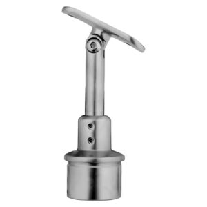
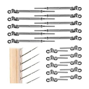
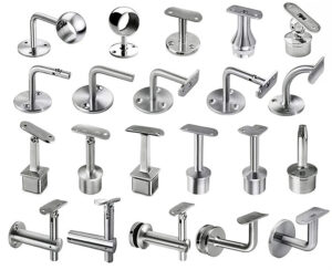
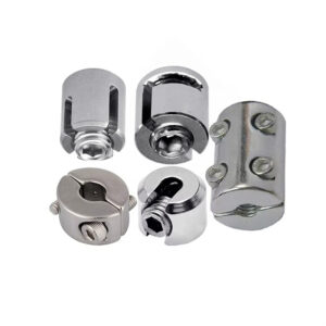
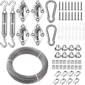
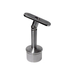
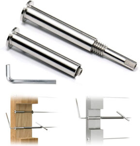
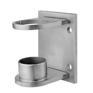
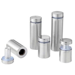
The substrate matters as much as the tube profile for bracket and fastener selection. Circle L brackets for round tube wall mounting are typically secured with self-tapping screws or lag bolts into wood framing, but concrete substrates require anchor bolts with appropriately rated embedment. The bracket design must accommodate both the tube OD and the fastener type dictated by the wall material — and those two requirements must be confirmed simultaneously. Sourcing a bracket that fits the tube but cannot accept the correct fastener for the substrate is a field problem that does not resolve without a replacement bracket.
| Component | What to Confirm | Risk if Mismatched |
|---|---|---|
| Circle L bracket | Bracket throat fits tube OD and wall thickness; mounting holes align with substrate (wood, concrete) | Bracket may not secure the tube; can cause reorder or field drilling |
| Fasteners (screws, lag bolts, anchor bolts) | Correct type for wall material (self-tapping/lag for wood; anchor bolt for concrete); length and diameter suit bracket | Inadequate anchoring, potential safety issue |
| End cap | Internal profile matches tube shape and wall thickness; finish matches tube | Loose fit or visual gap; may fall off |
| Elbow | Inner diameter and radius match tube OD and bend curvature | Mismatch forces drawing revision or replacement order |
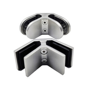
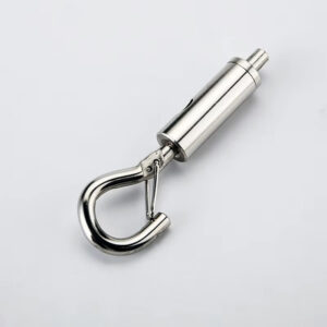
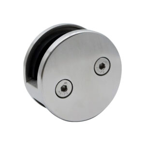
| Glass clamp | Clamp bore matches tube OD; design compatible with glass thickness | Glass instability or installation delay |
The review sequence that prevents most of these mismatches is straightforward: confirm tube OD and wall thickness first, then verify bracket throat against those dimensions, then confirm fastener type against substrate, then check end cap internal profile, then verify elbow and glass clamp bore. That sequence matters because earlier confirmations constrain later ones — a bracket selection made before tube OD is locked may be dimensionally incorrect in ways that only become visible when the end cap is checked against the same tube. Running the confirmations in the wrong order, or running them in parallel against unconfirmed dimensions, is the process error that generates the replacement orders and drawing revisions that make tube profile decisions expensive after the fact.
For round profile applications where bracket selection and run continuity are both part of the specification, reviewing Esang’s round tube handrail systems alongside the bracket compatibility detail gives procurement teams the component-level reference needed to close the verification sequence before order.
Tube profile in a stainless steel handrail project is a structural specification decision, not an aesthetic one that can be revisited after procurement begins. The profile controls which brackets seat correctly, which connectors align, which end caps fit, and which polishing direction is technically feasible. Once a BOM has been structured against round tube and samples are approved, switching to square tube does not substitute one pipe for another — it reopens every downstream component selection simultaneously.
The most useful thing a specification team or procurement buyer can confirm before any sample request is submitted is whether the profile decision has been made against confirmed tube OD, wall thickness, substrate type, finish category, and matched hardware geometry — not against a preliminary drawing or a visual preference. If any of those inputs are still approximate, the profile decision is not yet made. Closing that cluster before fabrication is where the schedule and rework risk actually sits.
Frequently Asked Questions
Q: Does this profile decision process apply if the tube is being specified for an outdoor coastal installation where corrosion resistance is the primary concern?
A: Profile selection still follows the same hardware-matching logic, but material grade becomes a prerequisite that must be resolved before the BOM is built. Coastal environments typically require 316-grade stainless steel rather than 304 to resist chloride-induced corrosion — and not all bracket, connector, or end cap hardware lines are available in both grades. If the matched hardware for a chosen profile is only catalogued in 304, the profile decision may need to be revisited alongside the grade decision, not separately from it. Confirm grade availability across the full hardware ecosystem — tube, brackets, connectors, end caps — before the profile is locked.
Q: Once tube profile, finish, and hardware are confirmed and the order is placed, what is the first fabrication-stage check that should happen before installation begins?
A: The first check is physical fit verification between the actual delivered tube OD and wall thickness against each hardware component — bracket throat, end cap bore, and elbow or connector seating — before any cutting or polishing begins. Mill tolerances under ISO 1127 and ASTM A554 mean delivered dimensions can vary from nominal, and a variance that is acceptable for the tube alone may affect how end caps seat or how connectors align. Running this check on delivered stock before fabrication starts costs minutes; discovering the mismatch after tube lengths are cut and polished costs a replacement order.
Q: At what point does a square tube specification become impractical for a project with multiple curved transitions?
A: Square tube becomes a high-risk specification when curved transitions fall below the minimum bending radius at which face-profile distortion remains visually acceptable — and that threshold is tighter for square tube than for round because corner stress concentration accelerates visible deformation. If a project has multiple radius landings or wrapped stairwells with tight centerline radii, the practical ceiling for square tube is reached sooner than drawings typically reflect. Round tube handles those transitions with more predictable dimensional outcomes. If curved runs are present and radius values have not been confirmed against square tube bending limits before design freeze, the profile decision should be treated as still open.
Q: Is a textured finish worth the additional cost compared to plain-finish tube for a high-traffic commercial corridor?
A: For high-contact commercial runs, textured finish typically justifies the cost difference by reducing visible wear accumulation over the project lifecycle. Plain or mirror-polished tube shows field scratches, installation scuffs, and minor contact damage as individual surface events; textured tube absorbs the same damage into an existing pattern that is not read as defects by most observers. The relevant planning factor is not finish cost alone but total maintenance cost over the handover period and warranty window — particularly in projects where construction traffic will contact the rail before final cleaning. The decision needs to be made before design freeze because it affects polishing direction and connector interface preparation, which cannot be reversed after fabrication specifications are set.
Q: How does this round-versus-square decision change if the project uses a glass panel infill system rather than cable or bar infill?
A: Glass panel infill introduces a glass clamp bore dependency that must be verified against tube profile the same way bracket throat and end cap fit are verified — but the tolerance sensitivity is higher because clamp seating affects both glass retention and visual alignment. Square tube glass clamps are designed around flat-face seating and a specific corner radius; round tube clamps use a circular bore. A clamp sourced for one profile will not seat correctly on the other, and the misalignment is typically visible at the glass face. If glass infill is part of the specification, the glass clamp bore must be added to the hardware verification sequence and confirmed against the locked tube OD and corner radius before any component is approved for order.