Specifying curved stainless steel handrails requires navigating a complex intersection of material science, fabrication capability, and safety compliance. A common misconception is that any desired radius is achievable, leading to designs that are either unmanufacturable or structurally compromised. The reality is that bend radius and its associated tolerances form a critical system of constraints that must be balanced from the outset to ensure a safe, code-compliant, and aesthetically successful installation.
Ignoring these constraints results in costly rework, project delays, and potential safety liabilities. With increasing emphasis on precision in modern construction and stricter enforcement of accessibility standards, a methodical approach to specifying handrail bends is no longer optional—it’s a fundamental requirement for architects, fabricators, and contractors.
Fundamental Principles of Bend Radius and Material Stress
Defining the Core Parameter
The internal bend radius (IR) is the primary variable governing handrail fabrication. It dictates the degree of deformation and internal stress within the stainless steel tube. This stress must remain below the material’s yield point to prevent cracking or failure. The minimum achievable radius is not arbitrary; it is a direct function of the tube’s outer diameter (OD) and, more critically, its wall thickness (T).
Material-Specific Multipliers
Stainless steel’s higher strength and lower ductility compared to aluminum or mild steel demand a conservative approach. Industry guidelines specify minimum bend radii as multipliers of wall thickness: 2xT for walls 1-6mm, 2.5xT for 6-12mm, and 3-4xT for thicker sections. This principle is non-negotiable. Attempting a tighter radius risks material failure, a mistake we’ve seen lead to entire batches of tubing being scrapped.
Strategic Implication for Design
These material constraints fundamentally limit how compact a handrail curve can be. Designers must prioritize these limits during the conceptual phase, not as an afterthought during fabrication. The bend radius sets the stage for all subsequent decisions regarding aesthetics, compliance, and manufacturability.
Key Tolerances: Radius, Angle, Ovality, and Wall Thinning
The Interdependent System
Specifying a nominal bend radius is insufficient. True quality is defined by controlling the associated tolerances—radius, angle, ovality, and wall thinning—which form an interdependent system. Adjusting one parameter often affects the others, requiring a holistic view during fabrication planning.
Precision and Structural Integrity
Radius tolerance (e.g., ±1mm) and angle tolerance (e.g., ±0.5°) ensure dimensional accuracy for proper fit-up during installation. However, the more critical tolerances concern the tube’s integrity. Ovality, the distortion of the circular cross-section, must be minimized. Excessive ovality weakens the tube and creates significant challenges for welding fittings or achieving a smooth, continuous grip surface.
The Critical Limit of Wall Thinning
As the tube bends, the material on the outer radius stretches and thins. Industry experts recommend capping this wall thinning at 20-25% to preserve the tube’s structural strength under load. The following table outlines the key tolerance parameters and their primary constraints.
Key Tolerances: Radius, Angle, Ovality, and Wall Thinning
| Parameter | Typical Tolerance | Key Constraint |
|---|---|---|
| Bend Radius | ±1 mm | Dimensional installation fit |
| Bend Angle | ±0.5° | Alignment accuracy |
| Ovality | Minimized | Structural integrity, welding |
| Wall Thinning | ≤20-25% | Preserve material strength |
Source: Technical documentation and industry specifications.
Stainless Steel Grades (304 vs. 316) and Their Impact on Bending
The Corrosion Resistance Driver
The choice between austenitic grades 304 (1.4301) and 316 (1.4401) is typically driven by environmental requirements. Grade 316, with its molybdenum content, offers superior resistance to chlorides and is specified for coastal or industrial applications. From a pure formability standpoint in the annealed (softened) condition, both grades exhibit similar bending characteristics.
The Critical Role of Material Condition
The material’s temper condition has a far greater impact on bending than the grade itself. Harder tempers, sometimes specified for increased yield strength, significantly reduce ductility. This necessitates a larger minimum bend radius compared to standard annealed stock. A design based on annealed material specs will fail if harder-temper tube is supplied.
The Need for Early Collaboration
This variability underscores a critical point: material certification and empirical behavior can differ between suppliers. Theoretical calculations must be validated with the fabricator who will process the specific stock. This shifts final specification authority to a collaborative gate, making early manufacturer consultation essential to mitigate project risk. The table below summarizes the primary considerations.
Stainless Steel Grades (304 vs. 316) and Their Impact on Bending
| Grade | Common Designation | Primary Driver |
|---|---|---|
| 304 | 1.4301 | Standard corrosion resistance |
| 316 | 1.4401 | High-chloride environments |
| Bending Impact | Condition is Critical | Key Consideration |
| Annealed State | Similar formability | Standard minimum radius |
| Hard Temper | Larger minimum radius | Increased strength trade-off |
Source: Technical documentation and industry specifications.
Choosing a Bending Process: Rotary Draw vs. Roll vs. Mandrel
Matching Process to Geometry
The selected bending process dictates the feasible geometries, final quality, and cost. There is no universal solution; each method serves a specific purpose. The wrong choice can lead to poor aesthetics, structural defects, or an inability to produce the required shape.
Rotary Draw for Precision
Rotary draw bending uses a die set to clamp and draw the tube around a fixed die. It offers high precision, excellent ovality control, and is capable of tight radii. This makes it the preferred method for consistent, high-quality standard elbows and bends with a constant radius.
Roll and Mandrel for Specialized Needs
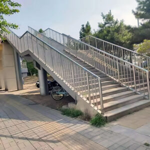
Roll bending passes the tube through a series of rolls to create large-radius sweeps or arcs, ideal for curved staircases. Mandrel bending, which employs an internal support rod, is essential for preventing collapse when achieving very tight radii on thinner-walled tubes. The required bending force scales disproportionately with material thickness, a key factor in tooling selection and cost. The comparison below clarifies the best applications for each method.
Choosing a Bending Process: Rotary Draw vs. Roll vs. Mandrel
| Process | Best For | Key Characteristic |
|---|---|---|
| Rotary Draw | Tight radii, elbows | High precision, low ovality |
| Roll Bending | Large-radius sweeps | Curved staircases, arcs |
| Mandrel Bending | Thin-walled, tight radii | Prevents tube collapse |
| Critical Factor | Bending Force | Scales with thickness |
Source: Technical documentation and industry specifications.
Short Radius vs. Long Radius Bends: Aesthetics and Function
The Space vs. Flow Trade-off
This choice represents a fundamental design and fabrication decision. Short radius bends (e.g., 50mm or a standardized 6-inch/152mm radius) save space and material, enabling compact layouts. Long radius bends, typically 1.5 times the tube diameter or larger, offer a smoother, more gradual guiding surface.
Fabrication and Aesthetic Implications
Long radius bends are gentler on the material, reducing stress and the risk of defects like excessive ovality. They also provide a more elegant, flowing aesthetic. Short radius bends, while efficient, are more challenging to fabricate consistently and may not provide the optimal hand-grip continuity required by some interpretations of code.
A Strategic Classification
The explicit industry classification between these types forces a clear decision. Stakeholders must weigh spatial efficiency against manufacturing reliability, aesthetic flow, and potential code compliance nuances. This choice directly impacts the pool of capable fabricators and the final installation’s performance.
Short Radius vs. Long Radius Bends: Aesthetics and Function
| Bend Type | Typical Radius Example | Primary Trade-off |
|---|---|---|
| Short Radius | 50 mm (tight) | Space and material efficiency |
| Short Radius | 152 mm (6-inch) | Standardized compact design |
| Long Radius | ≥1.5x Tube Diameter | Smoother guiding surface |
| Long Radius | Larger radii | Fabrication reliability, aesthetics |
Source: BS 6180:2011 Barriers in and about buildings. Code of practice. This standard provides guidance on the design of barriers and handrails to prevent injury, which includes specifying appropriate radii for bends to ensure safety and performance.
How Building Codes (IBC/OSHA) Influence Handrail Bend Design
Compliance as a Non-Negotiable Filter
Codes like the International Building Code (IBC) and OSHA regulations mandate specific requirements for handrails: continuous graspable surfaces, precise heights (34-38 inches), and defined load capacities (typically 200 lbs. concentrated or 50 lbs./linear foot). A bend must not create a pinch point, reduce the effective gripping diameter, or compromise structural integrity.
Radius and Continuity Requirements
The bend radius directly affects “graspability.” An overly tight radius can create an uncomfortable or non-compliant grip profile. Furthermore, codes require smooth transitions, often dictating the use of complex wreath bends at stair turns to maintain continuity. Standards like BS 6180:2011 provide explicit guidance on bend geometry to prevent injury, making adherence to such specifications a baseline for safe design.
Validating Fabrication Methods
The fabrication process must produce bends that meet these code mandates. For instance, excessive ovality from an improper bending technique could reduce the cross-sectional strength below required levels. Therefore, code compliance acts as a critical validation check, ensuring the chosen radius and fabrication method yield a safe, functional installation. It’s not just about the shape, but the integrity of the final product.
Practical Considerations: Flange Lengths and Fabrication Planning
The Minimum Flange Length Constraint
A frequently overlooked practical constraint is the minimum flange length—the straight section required between a bend and the tube end (or another bend) for the bending machine to grip the material. For standard rotary draw bending, this is typically 1.5 to 2 times the tube OD. Neglecting this renders a design unmanufacturable.
A Systems Approach to Planning
Flange length is one variable in an interdependent quartet, alongside material thickness, die opening, and bending force. Successful planning requires optimizing all four simultaneously. This systems approach prevents last-minute design changes and ensures the selected fabricator has the correct tooling.
Standardized vs. Custom Solutions
The market offers both standardized pre-bent components and fully custom fabrication. An efficient strategy often involves mixing both: using pre-configured elbows for simple 90-degree turns while reserving custom fabrication for complex, site-specific geometries. This balances cost, timeline, and precision. The table below outlines key planning factors.
Practical Considerations: Flange Lengths and Fabrication Planning
| Planning Factor | Typical Minimum | Purpose |
|---|---|---|
| Flange Length | 1.5–2x Tube OD | Machine grip requirement |
| Interdependent Variables | Systems Approach Needed | Determines Viable Bend |
| Material Thickness | Specific to project | Affects bending force |
| Die Opening | Matched to OD | Tooling compatibility |
Source: Technical documentation and industry specifications.
A Decision Framework for Specifying Handrail Bends
Define Non-Negotiable Constraints
Begin by establishing fixed parameters: applicable safety codes (ANSI A117.1 for accessibility, IBC for general compliance), spatial footprint limitations, and the selected tubing diameter and grade. These constraints form the immutable boundaries of the design.
Apply Material and Process Logic
Calculate the theoretical minimum bend radius based on wall thickness and material condition. Within the feasible range, evaluate the short vs. long radius trade-off for your application. Then, select the appropriate bending process (rotary draw, roll, mandrel) based on the required radius, quality tolerances, and geometry.
Engage Specialized Expertise Early
The most critical step is early engagement with a qualified fabricator. Their empirical knowledge is invaluable for validating tolerances, confirming flange lengths, and selecting the optimal process. This collaboration de-risks the project and ensures manufacturability.
Leverage Integrated Component Ecosystems
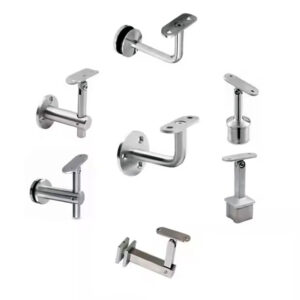
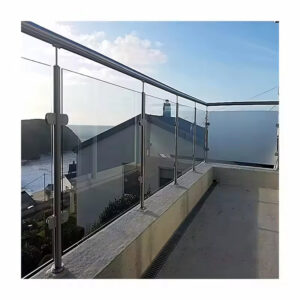
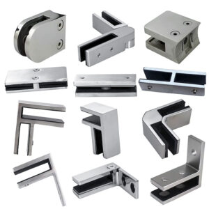
For many projects, the most efficient path is sourcing from suppliers offering compatible systems of bends, tubes, and fittings. This integrated approach, such as utilizing a comprehensive curved handrail system, minimizes compatibility errors and streamlines the specification-to-installation workflow, ensuring all components are engineered to work together.
Successful handrail specification hinges on three priorities: respecting the material science of stainless steel bending, integrating code compliance from the start, and collaborating with fabrication expertise during the design phase. Treating the bend as a simple geometric feature invites risk. Instead, view it as a engineered component with defined performance criteria.
Need professional guidance to navigate these technical specifications for your next project? The experts at Esang can provide the material knowledge and fabrication insight to ensure your curved handrail designs are both beautiful and buildable.
For a detailed consultation on your specific requirements, you can also Contact Us.
Frequently Asked Questions
Q: How do you determine the minimum bend radius for a stainless steel handrail tube?
A: The minimum radius depends on the tube’s outer diameter and, critically, its wall thickness. For stainless steel, conservative multipliers are applied: 2 times the wall thickness for 1-6mm sections, 2.5xT for 6-12mm, and 3-4xT for thicker walls. This stringent requirement, due to the material’s high strength and lower ductility, prevents cracking. This means designers must calculate this limit first, as it dictates the feasibility of compact handrail designs and prevents costly fabrication failures.
Q: What are the critical tolerances to specify for a high-quality handrail bend?
A: You must control four interdependent parameters: bend radius (±1mm), bend angle (±0.5°), ovality (cross-section distortion), and wall thinning (capped at 20-25%). Tight ovality control is vital for structural integrity and weldability. For projects where precision is paramount, expect leading fabricators to offer verifiable tolerance classes, making this control a key quality differentiator in procurement decisions.
Q: Does the choice between 304 and 316 stainless steel affect bendability?
A: Both austenitic grades have similar formability in their standard annealed condition. The critical factor is the material’s temper; harder tempers require a larger minimum bend radius than softer, annealed stock. This variability between material suppliers makes early consultation with your fabricator non-negotiable for design validation. If your project is in a corrosive environment requiring 316, plan to involve your fabricator early to confirm the bend radius based on their specific stock.
Q: When should you choose rotary draw bending over roll bending for a handrail?
A: Select rotary draw bending for precise, tight-radius bends like standard elbows, as it offers excellent ovality control. Use roll bending for creating large-radius sweeps or arcs, such as those for curved staircases. The bending force scales disproportionately with material thickness, so fabricators must model this for tooling compatibility. For projects with a mix of tight turns and long sweeps, plan to use both processes, which impacts your supplier selection and cost structure.
Q: How do building codes like IBC influence the allowable bend design?
A: Codes mandate a continuous, graspable surface and specific load capacities. A bend cannot create a pinch point, reduce the gripping surface, or compromise strength under load—excessive ovality or wall thinning from a tight radius could violate these rules. Standards like ANSI A117.1-2017 provide detailed requirements for handrail dimensions and continuity. This means your chosen radius and fabrication method must be validated against code to ensure a safe, compliant installation.
Q: What practical fabrication constraint is often overlooked in handrail design?
A: Designers frequently neglect minimum flange lengths, the straight section needed for the bending machine to grip the tube. This is typically 1.5 to 2 times the tube diameter between a bend and the tube end or another bend. Ignoring this renders a design unmanufacturable. For projects with complex geometries, you must adopt a systems approach, optimizing flange lengths alongside material thickness and bend radius during the planning phase to avoid costly redesigns.
Q: What is a strategic framework for specifying handrail bends?
A: Start by defining constraints: codes, space, and tube diameter. Second, calculate the minimum radius using wall thickness and conservative stainless steel multipliers. Third, choose between short-radius (space-saving) and long-radius (smoother, more reliable) bends. Fourth, select the bending process based on the radius and quality needed. Finally, engage a specialized fabricator early for validation. For efficiency, consider sourcing from suppliers offering compatible kits of bends and fittings to streamline the specification-to-installation workflow.