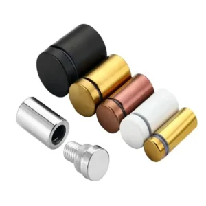
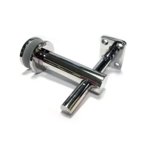
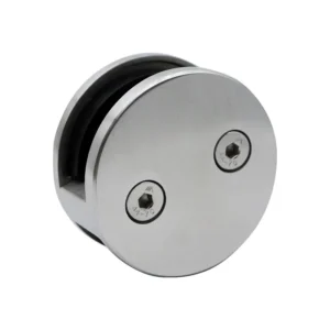
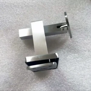
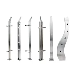
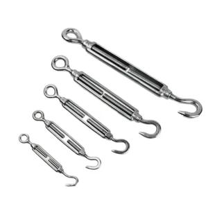
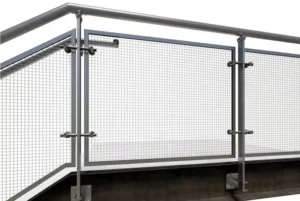
Bolting is the usual starting choice for a railing post base plate on steel when both faces of the receiving member are reachable and the hole pattern can be set out with proper edge distances. Welding becomes the better route when the receiving member is closed, when the base plate sits too close to a flange edge or web for nut and washer access, or when the project detail already calls for a shop-welded connection. The deciding conditions are physical: which steel member the base lands on, whether its back face can be reached, and whether the project has a documented welding procedure and qualified welders attached to the work.
Identify the Steel Member Receiving Each Post Base
Before comparing connection methods, establish what each post base actually lands on. A base plate bearing on a flat cap plate behaves very differently from one sitting on a hollow section, a beam flange tip, a beam web, or a secondary member such as a channel or angle, because the receiving geometry sets both fit-up and access.
Fit-up is the first consequence. A flat, continuous plate lets the base plate bed down across its whole footprint, so bolt tension or weld metal does what the detail intends. A base plate landing on a curved, tapered, sloped or narrow surface sits on partial contact, and any gap under the plate changes how the connection behaves when a guard load is applied at the top of the post.
Access is the second consequence, and it is the one that usually decides the method. A beam flange may be reachable from below in an open stairwell but buried in topping concrete or fireproofing elsewhere on the same project. A hollow section is closed by definition. Walk each base location on the drawings and mark the receiving member type, the surface condition at the base plate footprint, and what can physically be reached behind it.
Record this per location rather than per detail type. One generic “post base on steel” detail covering twenty positions will usually hide two or three positions where the real steel differs, and those are the ones that stall on site.
Compare Bolted Access With Welded Fit-Up
| Connection route | Geometry and access to define | Route-specific project controls | Evidence boundary |
|---|---|---|---|
| Bolted | Hole pattern, fastener specification, washer and nut access, and clearance for the selected installation sequence | Coordinate these items with the receiving member geometry and base plate | A stainless fastener property class does not establish torque-clamp force, shear, fatigue, or the joint design |
| Welded | Joint geometry and working access | Assign welding qualification responsibility and plan distortion control and finish restoration | Welder qualification scope does not prove that a particular joint, procedure, factory, or project is compliant |
| Either route | Identify whether the base meets a plate, tube, beam flange, beam web, or secondary support | Obtain supporting-steel designer confirmation of how the project actions transfer into the structure | Selecting bolting or welding alone does not close the load path |
The functional difference is straightforward: a bolted connection clamps the base plate against the steel using fasteners that must be installed, held and tightened; a welded connection fuses the base plate to the steel so that parent metal and weld metal melt and solidify as one joint. Everything that follows comes from that difference.
Bolting needs a defined hole pattern, a fastener specification, washer and nut access, and enough clearance for whichever installation sequence you intend to use. Conventional bolts require access to both sides of the connection during installation, which is why the Steel Tube Institute’s guidance on bolting to HSS members notes that closed hollow sections obstruct inside access. That guidance identifies shop-welded connection plates or specifically designed one-sided fixings as possible alternatives, not automatic substitutions, and it also points out that the connection design must check the receiving HSS wall itself for bearing, pull-out and distortion. A hole pattern that looks clean in plan can therefore be unusable on a closed tube until an engineered access or one-sided fixing detail exists.
Welding needs documented joint geometry, an assigned responsibility for welding qualification, working access for the welder in the as-built position, distortion control, and a plan for restoring the stainless finish afterward. It removes the two-sided access problem but replaces it with process control problems that have to be resolved before fabrication rather than on site.
Neither method is inherently stronger in the abstract. The comparison is between an access and tolerance problem on one side and a procedure and finish problem on the other, assessed location by location against the steel you identified.
Define Hole, Fastener, Joint, and Base Plate Geometry
Whichever method you select, the connection only becomes buildable once its geometry is written down as dimensions rather than described in words. For a bolted base, that means the hole pattern with its spacing and edge distances relative to both the base plate and the receiving member, the hole size and type, the fastener specification including grade and length, washer arrangement, and the clearance envelope a wrench or socket needs to reach each nut.
Fastener property class deserves particular care on stainless work. ISO 3506-1:2020 specifies mechanical and physical properties and property classes for corrosion-resistant stainless bolts, screws and studs tested between 10 and 35 °C, and its scope explicitly excludes requirements for torque and clamp force, shear strength, fatigue resistance and weldability. A property class on a purchase order therefore tells you what the fastener material will do in tension under those test conditions; it does not tell you the installation torque, the shear capacity of the joint, or whether the bolt group suits the actions at that post. Those come from the connection design.
For a welded base, the geometry to define is the joint itself: the preparation, the weld type and size, and the position in which it will be made. Joint preparation depends on the process, the access available and the material thickness, as Steel Construction Info sets out for structural steelwork fabrication, so a joint detailed for a bench position may not be achievable with a welder working overhead against a soffit.
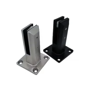
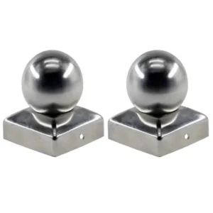
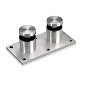
The base plate itself is the third geometry to pin down, because its thickness, footprint and hole or weld layout have to suit both the post and the steel beneath. Surface mount base plates suit flat, accessible bearing surfaces where the fastener pattern fits inside the plate footprint; heavy duty base plates give a larger footprint and more material to work with where the connection design calls for it. Setting the plate dimensions after the hole pattern has been fixed is a common sequencing mistake, because it leaves edge distances short on the plate itself.
Plan Welding Qualification, Distortion, and Finish Restoration
| Welding planning item | Project definition to make explicit | Decision boundary |
|---|---|---|
| Joint geometry | Document the joint geometry for the selected post base and receiving steel | Joint geometry does not establish welding qualification |
| Qualification responsibility | Identify responsibility for the applicable welding qualification | ISO 9606-1 addresses qualification testing of welders; it does not prove that a particular joint, procedure, factory, or project is compliant |
| Working access | Confirm working access for the documented joint geometry | Access must be assessed for the project location and connection detail |
| Distortion control | Define the distortion-control plan for the welded route | The control remains specific to the selected connection and project |
| Finish restoration | Define the finish-restoration plan after welding | The restoration plan must correspond to the project finish |
A welded post base is only as good as the controls planned around it, and those controls are separate items that each need an owner. Joint geometry, qualification responsibility, working access, distortion control and finish restoration are five distinct definitions; documenting one does not deliver the others.
Qualification is the item most often collapsed into a single piece of paper. Welding procedure control and welder qualification are separate controls. BS EN ISO 9606-1 tests welders within ranges of process, consumable, joint type, position and material, which means a welder’s certificate confirms that person has been tested within those ranges. It does not approve a project, a factory, or the particular joint in your detail. The welding procedure applicable to that joint is a separate document, and who holds responsibility for producing and approving it should be named before fabrication starts.
Distortion follows directly from how fusion welding works. The molten pool solidifies and the weld metal shrinks, and that shrinkage pulls on the surrounding steel. Steel Construction Info notes that weld shrinkage makes sequencing relevant to distortion, which is why weld sequence and procedure control are substantive engineering choices rather than workshop habits. On a railing post base, shrinkage can tilt a post out of plumb or lift a base plate corner off the receiving steel, and both show up as fit-up errors in the infill rather than as obvious weld defects.
Finish restoration is the fifth item and the one most relevant to exposed and coastal work. Welding destroys the passive layer and the mechanical finish in the heat-affected zone, so the restoration method has to be defined to match the specified finish and exposure before anyone strikes an arc. Whether a completed welded base is accepted and released for loading is decided by the project’s approved procedure and its designated approver, not by the fabricator’s own sign-off.
Coordinate Load Transfer With the Supporting-Steel Designer
Selecting bolting or welding does not close the load path. It defines how the post base attaches to one steel member; the supporting-steel designer still has to confirm how the project actions at the top of the post travel through that connection and into the structure.
That confirmation covers things the railing hardware specification cannot address. A post base fixed to a beam flange tip applies a local moment and may need the flange checked for bending, or a stiffener added. A base bolted to a hollow section requires the receiving wall to be checked for bearing, pull-out and distortion, as the Steel Tube Institute guidance sets out for HSS connections. A base landing on a secondary member may be transferring load into something sized for self-weight and cladding, not for guard actions.
Give the designer what they need to do that check: the post spacing, the design guard loads being applied, the height at which they act, the base plate footprint and fixing layout you propose, and the receiving member identified at each location. Where the answer changes the hardware, it is better that it changes before the posts are cut to length.
If the supporting steel turns out not to suit the proposed connection at a given location, the resolution belongs with the structural designer rather than with a field adjustment. Enlarging holes, moving a base plate off its marked position or adding unplanned welds all change the connection that was checked.
Freeze the Connection Route in the Approved Project Detail
The connection method stops being a discussion point once it is recorded in an approved detail for each base location, with the geometry, the controls and the load-path confirmation attached to it. Until that happens, two trades can be working to different assumptions about the same base plate.
A frozen detail carries the receiving member type at that location, the selected method, the hole pattern and fastener specification or the joint geometry and applicable welding procedure, the base plate type and dimensions, the finish and any restoration method, and the designer’s confirmation that the connection suits the actions. Shop drawing review is where these come together, and it is the point at which a mismatch between the railing package and the steel package is cheap to fix.
Where locations differ, keep them as separate details rather than variations on one. A project with four bases on cap plates, two on a hollow section and one on a beam web has three connection conditions, and merging them into a single note is what produces the site query later.
For a useful discussion with a railing supplier about stainless steel posts and base plates, have the steel fabrication drawings showing member types and sizes at each base, the mounting detail with available edge distances and access, the specified stainless grade and finish, the exposure the installation faces, and the guard loading and post spacing being designed to. With those in hand, the bolted or welded decision at each location can be settled on geometry rather than argued from preference.
Frequently Asked Questions
Q: Can the same bolted or welded post-base detail be repeated at every railing location?
A: Only after the receiving steel and access conditions are checked for each repeated condition. Group locations by whether the base meets a plate, tube, beam flange, beam web, or secondary support; treat locations with different geometry or installation access as separate connection conditions until the project detail confirms otherwise.
Q: What should be included in a design-review or procurement package before the connection route is selected?
A: Include a location schedule linking each post base to its receiving steel, the base-plate geometry, the proposed hole and fastener details or welded-joint geometry, installation access and sequence, and the required finish. For a welded route, also assign qualification responsibility and define distortion control and finish restoration; obtain separate confirmation of load transfer into the supporting steel.
Q: What if the washer or nut cannot be reached after the base plate is positioned?
A: Keep the bolted route open until the actual clearance and installation sequence show that the fastener, washer, and nut can be installed as detailed. If that access cannot be demonstrated, the connection detail or route needs project-specific resolution before release rather than an improvised field change.
Q: Is a stainless fastener property class enough to approve a bolted post base?
A: No. The property class identifies a fastener characteristic, but it does not establish torque-clamp force, shear, fatigue, or the adequacy of the joint and anchor design. The review package should identify the selected fastener specification and the separate project evidence used for those applicable connection checks.
Q: Does a qualified welder make a welded post-base detail project-compliant?
A: No. Welder qualification addresses its stated qualification scope; it does not by itself approve a particular joint, procedure, factory, or project. Verify the documented joint geometry, applicable welding procedure and qualification responsibility, working access, distortion-control plan, and finish-restoration plan for the selected connection.