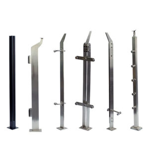
Installing stainless steel posts on concrete is a critical structural connection, not a simple hardware task. The integrity of a railing, canopy, or sign depends on the correct selection and installation of anchor bolts. A mismatch between anchor type, concrete condition, and torque specification is a common point of failure, leading to costly repairs and liability. Professionals must navigate a maze of technical requirements to ensure a durable, code-compliant installation.
This process demands precision. Concrete is unforgiving; a misdrilled hole or an over-torqued bolt compromises the entire assembly. The shift towards using certified, all-in-one stainless steel component kits directly addresses the installer’s pain point of sourcing compatible parts. This article provides the decision framework and technical specifications needed to execute a flawless installation, focusing on the critical interdependencies between surface preparation, hardware selection, and controlled installation.
Choosing the Right Anchor Bolt Type for Your Project
Defining the Anchor’s Role
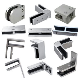
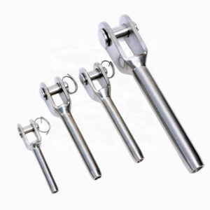
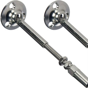
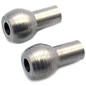
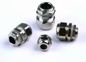
The anchor bolt is the fundamental load-transfer device. Its primary function is to develop the full strength of the post assembly by engaging with the concrete substrate. The choice is not a matter of preference but of engineering. For cured, structural concrete, mechanical expansion anchors are the standard. These anchors, such as wedge or sleeve types, create a secure lock through outward force against the concrete borehole walls. The selection process is a critical path dependency; an incorrect choice based on assumed substrate conditions cascades into structural compromise.
Matching Anchor to Application
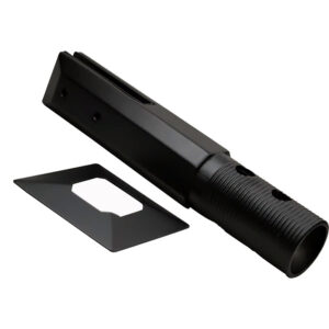
The decision matrix is driven by three factors: the post base design, the anticipated load (shear and tension), and the concrete’s age and condition. A 1/2″ diameter x 4″ long stainless steel expansion bolt is a common specification for standard railing posts. For higher loads or where precise alignment is crucial, drop-in anchors offer a flush-mounted option. Industry experts recommend consulting the anchor manufacturer’s published evaluation reports, which are based on standards like ICC-ES AC193 Acceptance Criteria for Mechanical Anchors in Concrete Elements. This ensures the selected product has been tested and approved for the intended structural use.
The Strategic Value of Integrated Kits
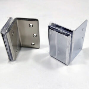
We compared sourcing individual components versus pre-engineered kits and found the latter significantly reduces risk. The market’s move towards all-in-one kits, which consolidate certified stainless steel anchors, bolts, and trim, reflects a strategic shift. It addresses the fragmented supply chain and eliminates compatibility guesswork. For the specifier, this curation represents value through risk mitigation, transforming the procurement process from a sourcing challenge into a guaranteed system solution.
| Anchor Type | Typical Size | Best For |
|---|---|---|
| Expansion Bolt | 1/2″ x 4″ long | Cured concrete |
| Drop-in Anchor | Varies by load | Standard mechanical lock |
| All-in-one Kit | Certified components | Simplified sourcing |
Source: ICC-ES AC193 Acceptance Criteria for Mechanical Anchors in Concrete Elements. This standard establishes the test methods and qualification requirements for post-installed mechanical anchors, ensuring the selected bolt type meets code-mandated performance for structural connections.
Critical Steps for Preparing the Concrete Surface
Assessing Substrate Integrity
The anchor is only as strong as the concrete it grips. The first non-negotiable step is a thorough assessment of the substrate. The concrete must be sound, free of cracks, spalling, or old repair material. Tapping the surface can reveal hollow spots where the concrete has delaminated. Anchoring into compromised material guarantees failure. This phase underscores a fundamental insight: the high cost of retrofit and associated liability drives specification towards premium materials and meticulous procedures from the outset.
Execution of Surface Preparation
Once integrity is confirmed, preparation is mechanical. The surface must be clean and free of all debris, paint, sealers, or curing compounds. A wire brush, grinder, or scarifier is often required to achieve a clean, profiled substrate. Easily overlooked details include checking for moisture within the concrete slab, as some anchor types have specific requirements. The unanimous emphasis on this step reflects a risk-averse culture. For project managers, enforcing strict compliance here is a justifiable investment, as shortcuts immediately introduce liability and void performance warranties.
Drilling and Hole Preparation: Avoiding Common Mistakes
Precision in Drill Specifications
Drilling is where theory meets practice, and precision is paramount. The hole diameter must exactly match the anchor manufacturer’s specification—a 1/2″ anchor requires a 1/2″ carbide-tipped hammer drill bit. Depth is equally critical; it must exceed the anchor’s minimum embedment length to allow for debris clearance. For a 4″ long anchor, a 4.5″ deep hole is typical. Using a depth stop on the drill is mandatory for consistency. In my experience, the most common field error is eyeballing depth, which leads to inconsistent embedment and compromised holding values.
The Non-Negotiable Cleanout
After drilling, the hole is not ready. It is filled with concrete dust that acts as a lubricant, preventing the anchor from achieving full contact and expansion. Complete debris removal using a dedicated hole brush, vacuum, or compressed air is the single most important step for ensuring published load capacities. This technical requirement highlights the gap between professional and amateur execution. The availability of detailed guides for this precise work indicates a market where suppliers are capturing users who demand contractor-grade results and are willing to follow disciplined processes.
| Parameter | Specification | Critical Action |
|---|---|---|
| Hole Diameter | Match anchor exactly | Use carbide-tipped bit |
| Hole Depth | Exceed embedment length | 4.5″ for 4″ anchor |
| Debris Clearance | Complete removal | Brush, vacuum, air |
Source: Technical documentation and industry specifications.
Proper Torque Specifications for Stainless Steel Anchors
Understanding Torque’s Function
Applying correct torque activates the anchor’s holding mechanism. For an expansion anchor, it drives the cone or wedge to expand the sleeve, creating the necessary outward pressure against the concrete. The specified torque value is engineered to achieve this without over-stressing the bolt threads or crushing the concrete at the surface. Using an impact wrench is a critical mistake; it can instantly over-torque, causing failure. A calibrated torque wrench is the only acceptable tool.
Adhering to Manufacturer and Standard Specifications
Final torque values are not universal. For a 1/2″ stainless steel expansion anchor, a range of 40-50 ft-lbs is common, but the manufacturer’s printed specification is definitive. This requirement is rooted in material science standards like ASTM F1554 Standard Specification for Anchor Bolts, which establishes mechanical property baselines. The specified use of Grade 304 or 316 stainless steel for all hardware is a direct response to corrosion-induced failures. Strategically, competing on price with lower-grade materials transfers immense risk to the installer. Marketing must emphasize lifecycle cost and risk mitigation.
| Anchor Size | Final Torque Range | Critical Tool |
|---|---|---|
| 1/2″ Stainless Steel | 40-50 ft-lbs | Calibrated torque wrench |
| All sizes | Follow manufacturer spec | Never impact wrench |
Note: Over-torquing can strip threads or crush concrete.
Source: ASTM F1554 Standard Specification for Anchor Bolts, Steel, 36, 55, and 105-ksi Yield Strength. While focused on steel grades, this standard underpins the mechanical property requirements for anchor bolts, establishing the basis for proper installation torque to achieve specified yield strength without failure.
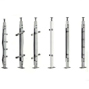
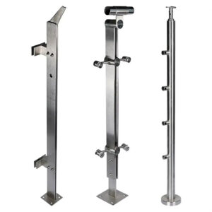
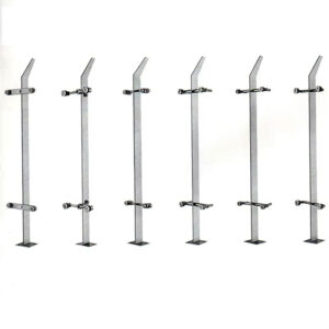
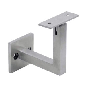
How to Securely Attach the Post to the Anchor Base
The Connection Sequence
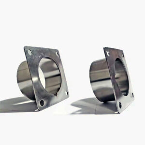
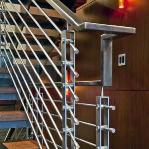
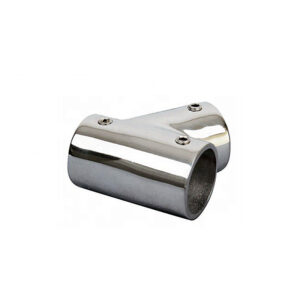
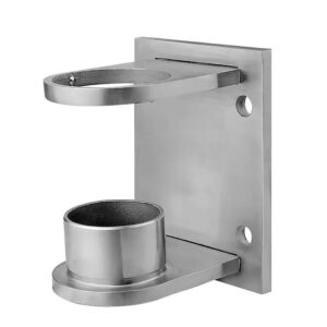
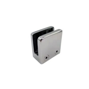
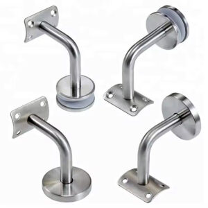
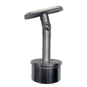
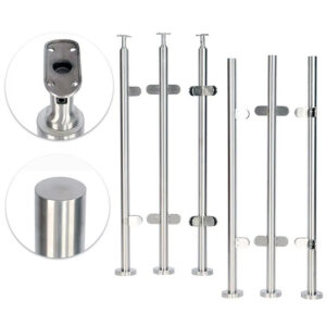
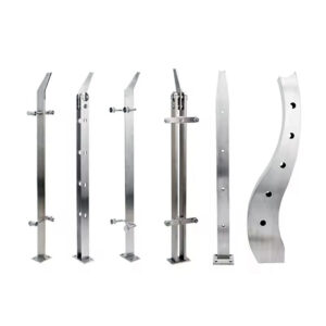
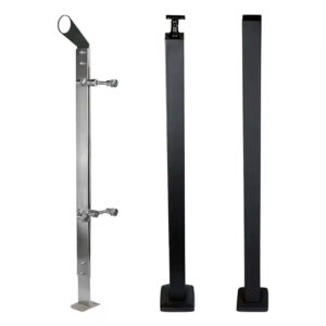
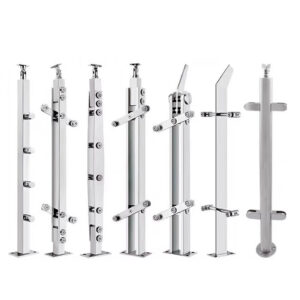
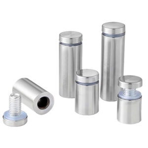
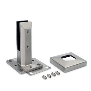
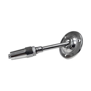
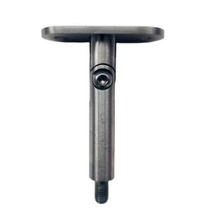
With the anchor bolts properly torqued and securing a metal base plate to the concrete, the final step is attaching the stainless steel post. This is typically done with lag bolts or hex bolts (e.g., 5/16″ x 3″) through pre-drilled holes in the post and into the base plate. The goal is a snug, firm clamp that eliminates movement. This stage integrates the structural solution with the finished visual appeal, a key market demand. It’s where the unseen engineering meets the user’s daily experience.
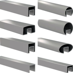
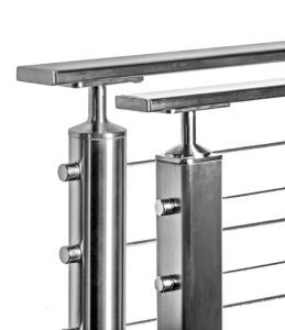
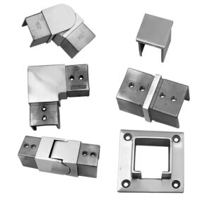
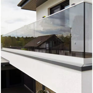
Integrating Aesthetic and Function
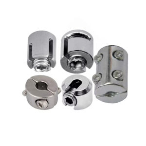
The common specification for decorative screw covers, trim boxes, or wood boots to conceal hardware is not an afterthought. It is an integrated system requirement. This insight reveals that product development must prioritize aesthetic integration equally with structural performance. The visual finish is a primary differentiator for end-user satisfaction. It also enables a product ecosystem strategy, driving aftermarket revenue through compatible, branded accessories that ensure a clean, professional appearance for projects involving stainless steel railing posts and components.
Special Considerations for New Concrete Footings
Engineering for Stability and Code
Installing posts on new footings requires forethought. The footing must be engineered for stability, accounting for dead loads, live loads, and environmental forces. Minimum guidelines suggest an 8″ to 12″ diameter footing extending below the local frost line—often 30″ to 42″ deep—to prevent heaving. This is where geographic location becomes a primary engineering variable, governed by codes like ACI 318 Building Code Requirements for Structural Concrete. Frost line depth and wind load tables directly dictate foundation dimensions.
The High-Wind and Reinforcement Escalation
In high-wind or seismic regions, standard guidelines escalate. The footing diameter often increases, and internal reinforcement with an embedded steel rebar cage becomes mandatory. A critical operational insight emerges here: confirming final structural drawings and anchor placement before the concrete pour is a mandatory gate. A frequent bottleneck occurs when foundational work is completed based on preliminary sketches, leading to irreversible errors in anchor placement once the final post design is confirmed.
| Requirement | Minimum Guideline | High-Wind Region Escalation |
|---|---|---|
| Footing Diameter | 8″ to 12″ | Larger, reinforced |
| Footing Depth | Below frost line | 30″-42″ typical |
| Internal Reinforcement | Standard | Embedded steel cage |
Source: ACI 318 Building Code Requirements for Structural Concrete. ACI 318 governs the design and construction of structural concrete foundations, providing the engineering basis for footing dimensions, depth relative to frost lines, and reinforcement requirements for stability under load.
Preventing Corrosion and Ensuring Long-Term Durability
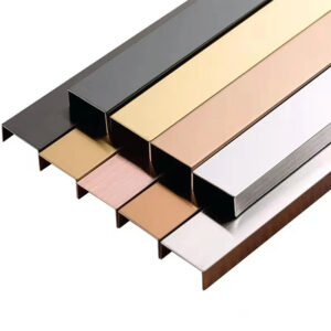
The Imperative of Material Compatibility
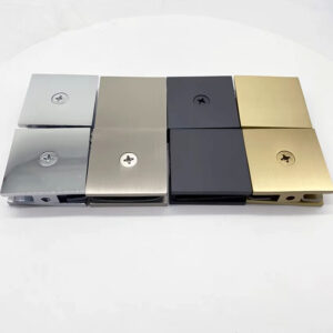
Long-term durability is secured through foresight in material selection. Specifying 18-8 or 316 stainless steel for all hardware—anchors, bolts, and base plates—prevents galvanic corrosion between dissimilar metals. This is especially critical in outdoor, humid, or coastal environments where salt spray accelerates corrosion. This uncompromising specification is a direct, liability-driven practice. Using mixed metals, like a carbon steel anchor with a stainless post, creates a galvanic cell that will corrode the carbon steel rapidly.
The Lifecycle Cost Justification
The strategic implication extends beyond the initial install. Using premium, compatible materials minimizes future maintenance, retrofit costs, and failure liability. It reinforces brand trust, as systems that endure without degradation reduce warranty claims and support a reputation for quality. This justifies the initial specification premium over the project’s total lifespan. The material criteria are defined by standards such as ASTM A276/A276M Standard Specification for Stainless Steel Bars and Shapes, which ensures the selected grades meet necessary corrosion resistance.
| Component | Material Specification | Critical Environment |
|---|---|---|
| All Hardware | 18-8 or 316 Stainless Steel | Outdoor, humid, coastal |
| Bolts & Anchors | Grade 304 acceptable | General outdoor use |
| Goal | Prevent galvanic corrosion | Full material compatibility |
Source: ASTM A276/A276M Standard Specification for Stainless Steel Bars and Shapes. This standard specifies the chemical composition and mechanical properties for stainless steel grades, providing the material criteria to ensure the selected hardware (posts, anchors, bolts) meets necessary corrosion resistance and strength.
A Step-by-Step Installation Checklist for Success
The Pre-Installation Gate
A disciplined checklist begins with definitive pre-work. First, conduct a substrate assessment and finalize the design, including load calculations. Second, procure all components, prioritizing standardized stainless steel parts or a certified all-in-one kit. Third, verify all tools are on-site: a hammer drill with carbide bits, a depth stop, cleaning tools, a calibrated torque wrench, and the correct driver bits. This preparation eliminates mid-installation delays and errors.
The Execution and Verification Sequence
The execution phase follows a strict sequence: 1) Mark and verify hole locations. 2) Drill to exact diameter and depth. 3) Thoroughly clean each hole. 4) Set anchors and hand-tighten. 5) Use the torque wrench to achieve the specified value in a cross-pattern if multiple anchors. 6) Attach the post to the base plate. 7) Install aesthetic covers. The evolution of this process points toward a key opportunity: digital configuration tools that automate material lists and engineering details based on user inputs, reducing errors and building trust.
Successful installation hinges on three core priorities: definitive substrate assessment, selection of certified compatible components, and disciplined adherence to torque specifications. These steps transform a collection of parts into a durable, code-compliant structural system. Need professional-grade stainless steel posts, anchors, and integrated mounting solutions for your next project? Explore the engineered systems and technical resources available at Esang. For specific project inquiries or technical support, you can also Contact Us.
Frequently Asked Questions
Q: How do you select the correct mechanical anchor for mounting a stainless steel post to cured concrete?
A: The choice depends on your post base design and load requirements, with expansion bolts (like a 1/2″ diameter x 4″ long anchor) and drop-in anchors being standard for cured concrete. This decision is foundational; an incorrect selection can lead directly to structural failure. For projects where supply chain complexity is a concern, using a certified all-in-one kit that ensures component compatibility is a strategic move to mitigate sourcing errors and warranty issues.
Q: What are the critical steps for preparing a concrete hole to ensure anchor performance?
A: You must drill a hole with a diameter that exactly matches the anchor specification and a depth that exceeds the anchor’s embedment length—for example, drill 4.5″ deep for a 4″ anchor. The most critical step is thorough cleaning using a brush, vacuum, or compressed air to remove all dust, as residue prevents proper anchor seating. This means even for DIY projects, investing in professional-grade cleaning tools is non-negotiable to achieve the engineered holding capacity and avoid liability from a failed installation.
Q: What torque should be applied to a 1/2″ stainless steel expansion anchor, and why is the tool choice critical?
A: A final torque of 40-50 ft-lbs is typical, but you must always follow the manufacturer’s published specification. Using a calibrated torque wrench is essential, as an impact wrench can easily over-torque, stripping threads or damaging the concrete. This precise requirement underscores that competing on price with lower-grade tools or materials introduces high risk; the lifecycle cost and risk mitigation provided by proper, certified equipment justify the initial investment.
Q: How do building codes and standards govern the installation of anchors for structural posts?
A: Anchor design and capacity are governed by ACI 318, which includes specific chapters on anchorage to concrete. Furthermore, the mechanical anchors themselves must be evaluated and accepted per protocols like ICC-ES AC193 for code compliance. This means you cannot rely solely on vendor claims; you must verify that the selected anchor system has an evaluation report demonstrating it meets these critical structural safety standards for your specific loading conditions.
Q: What special considerations are needed for installing posts into new concrete footings?
A: New footings must be engineered for stability, with a typical minimum diameter of 8″ to 12″ extending below the local frost line (often 30″-42″ deep). In high-wind regions, this escalates to a reinforced footing with an embedded steel cage. This geographic dependency means you must confirm final structural drawings, including the exact post location and anchor embedment, before the concrete pour to avoid irreversible and costly errors during later installation stages.
Q: Why is specifying a specific grade of stainless steel critical for all hardware in this application?
A: Using 18-8 (304) or 316 stainless steel for anchors, bolts, and base plates prevents galvanic corrosion between dissimilar metals, which is a primary failure mode in outdoor or coastal environments. This uncompromising material specification is a direct response to corrosion-related warranty claims and liability. For projects in humid or corrosive environments, this means the initial premium for 316 stainless steel is a justifiable investment that minimizes future maintenance costs and protects against structural degradation over the project’s total lifespan.
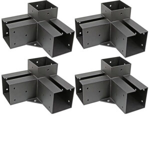
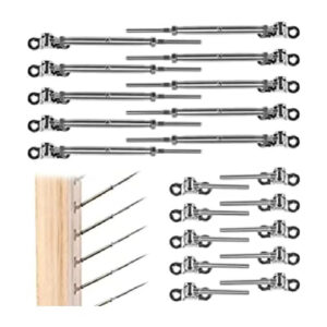
Q: What is the strategic advantage of using an “all-in-one” anchor and post mounting kit?
A: These kits consolidate certified stainless steel anchors, bolts, and trim from a single source, directly addressing the installer’s pain point of sourcing compatible parts from a fragmented supply chain. They provide assurance that all components are designed to work together, which simplifies procurement and reduces the risk of specification errors. This reflects a broader shift where value is moving from component manufacturing to curation and compatibility assurance, rewarding suppliers who reduce complexity and risk for the end user.