Most bracket selection errors are committed at the procurement stage, long before anyone measures a wall or checks an anchor point. A bracket chosen for its finish or profile may pass a visual check at delivery and still produce an installation that shifts under load, fails a clearance audit, or requires partial demolition when the wall condition turns out to differ from what the catalog drawing assumed. The decision that prevents that outcome is not a product comparison—it is a sequence: substrate type, required projection, expected point load, and accessibility geometry must be resolved before finish or shape enters the conversation. What follows will help you identify where the real selection criteria sit and what changes when any one of those four variables shifts.
Which bracket variables matter before shape and finish
Material and structural capacity are the first variables that lock in your options, and they do so before finish has any relevance. A bracket made from solid stainless steel or structural steel carries a fundamentally different load path than one made from a lighter alloy or surface-treated mild steel, regardless of whether both look similar in a catalog image. That distinction matters because bracket selection is not a stylistic exercise—it is a configuration input that determines how the installed system will behave under sustained and impact loading over the life of the installation.
The practical sequence is: material first, then projection geometry, then finish. Teams that reverse this order often discover the structural problem only after the finish has been specified and procurement is closed. Changing a bracket family at that stage typically means renegotiating lead times, absorbing cost differences, and in some cases redrawing the wall attachment plan if the new bracket requires different anchor spacing or a deeper substrate engagement.
Shape and finish should be treated as the final narrowing step within a bracket family that has already been validated on structural and geometric grounds. If two bracket profiles are structurally equivalent and both satisfy the projection and anchoring requirements, then finish becomes a meaningful differentiator. If only one profile meets the load and projection criteria, finish is not a variable—it is a constraint.
How projection distance changes anchoring and stiffness
Projection distance is not just a measurement of how far the rail sits from the wall—it is a mechanical amplifier. Every additional increment of projection increases the moment arm acting on the anchor point when a downward or lateral load is applied to the rail. A bracket with a longer reach transfers more bending stress to its wall connection than a shorter bracket under the same applied load, which means the anchor engagement depth and the substrate strength become more critical as projection increases.
This is why brackets sized to a catalog drawing can underperform in the field: the drawing reflects the nominal projection against an assumed substrate, but the actual installation may involve finish layers, pack-out spacers, or uneven surfaces that add distance between the anchor point and the back face of the bracket. Even a small increase in effective projection—say, 15 to 20 millimeters added by tile buildup—changes the load distribution at the anchor. For longer-reach brackets on commercial stairs, that difference can be the margin between a stiff installation and one that develops perceptible movement over time.
Anchoring into structural backing rather than finishing material is the mechanism that preserves load path integrity as projection increases. A surface-mounted anchor that skips the structural layer may hold under static load but lose engagement under repeated lateral loading, which is precisely the condition that occurs on heavily trafficked stairs. The implication for specification is direct: as you increase projection to clear wall features, handrails, or accessibility envelopes, the anchoring requirement should be reviewed in parallel, not treated as a fixed detail from a prior project.
Where wall condition overrides the catalog default
The catalog drawing for any bracket family assumes a consistent, solid substrate at the mounting face. That assumption is often false on real projects, and the degree to which it is false determines whether the installation performs as intended or becomes a structural liability that is difficult to audit after the fact.
Hollow partition walls, tiled surfaces, and concrete cores can all appear within the same corridor or stair run. A bracket selected for concrete mounting will require different anchor hardware and may need a different projection length if the same run crosses a framed partition with hollow backing. If the bracket family is not selected to account for this variation—or if the installer defaults to the anchor pattern used on the concrete section when reaching the partition—the effective anchor engagement drops significantly. The installation may look identical from the front, but the load path is compromised at the weaker sections.
ASTM E894-88(2004), which covers anchorage of permanent metal railing systems, frames the core issue clearly: anchorage performance is a function of substrate conditions, not just hardware specification. A bracket and fastener combination that meets load requirements in one substrate condition may not maintain the same performance in a different one. This is not a fringe scenario—it is a standard project-level reality that should be addressed during the specification phase rather than delegated to installer judgment on site.
The downstream consequence of ignoring wall condition at specification is a mixed-quality installation: some brackets holding correctly, others underperforming in ways that are invisible at handover but detectable under load or at a post-occupancy compliance review. Correcting that after finishes are complete typically involves opening walls, replacing anchors, and in some cases repositioning the bracket family entirely to accommodate the actual substrate depth. Explore the available Mounting Hardware & Brackets options with substrate conditions in mind before specifying a single bracket family across a full project run.
Why accessibility clearance must be checked with bracket geometry
Bracket projection is the geometric variable most commonly overlooked in accessibility review, because it is typically treated as a structural detail rather than a clearance input. The position of the rail relative to the wall is a direct function of bracket reach, and that position must satisfy the graspability and clearance requirements that apply to the installation—requirements that do not bend to accommodate a bracket that was chosen without checking the geometry first.
The Access Board’s ADA-IBC Comparison guidance for Chapter 5 establishes that installed rail position is subject to accessibility verification, not just the rail’s cross-sectional shape. A bracket that positions the rail too close to the wall can compromise the clear knuckle space needed for a full grip, while a bracket that reaches too far may create a projection hazard or push the rail outside the envelope that a mounting surface or adjacent structure can accommodate. Neither problem is obvious from a catalog drawing alone.
The review check that prevents this is straightforward but must happen before fabrication: take the actual wall face dimension, add any finish or pack-out layers, add the bracket projection as installed, and confirm that the resulting rail centerline position satisfies both the structural anchoring requirement and the accessibility clearance. For more on how rail geometry interacts with gripping surface compliance, the detailed guidance in ADA-Compliant Stainless Steel Handrail Diameter and Gripping Surface Standards works through the geometric inputs systematically. If that check is not performed until installation is underway, the bracket family may need to change—and at that point, the lead time and cost consequences are no longer avoidable.
How to separate light-duty and heavy-use bracket paths
The distinction between light-duty and heavy-use bracket paths is not primarily about bracket shape or material grade—it is about load distribution across the full run and what happens at each anchor point when that distribution is stressed. A bracket path that is adequate for a low-traffic residential corridor can be systematically insufficient for a commercial stair where lateral and downward loads are concentrated repeatedly at the same anchor points throughout the day.
Spacing and bracket count are the two variables that define whether a path can handle sustained heavy use. Exceeding the spacing threshold between supports allows the rail to deflect between anchor points, transferring load concentrations away from the bracket base and into the rail tube itself. For longer runs, insufficient bracket count has the same effect: sections of rail between brackets carry load that should be distributed to the wall.
| Support Requirement | Threshold Value | Why It Matters |
|---|---|---|
| Maximum bracket spacing to prevent sagging | 48 inches (4 feet) | Critical for load distribution and stability along the rail. |
| Minimum bracket count for rails over 5 feet | 3 brackets | Ensures sturdy support for longer rails, especially in heavy-use applications. |
For heavy-use applications, the practical implication of these thresholds is that spacing and count should be planned conservatively, not minimally. A rail run that technically meets a minimum bracket count may still underperform if the bracket family is not matched to the expected point load at each anchor—particularly at stair nosing positions, landings, and transitions where users shift weight and loading becomes directional rather than purely downward. The decision about bracket path is therefore inseparable from the decision about bracket type: you cannot arrive at the right count without knowing the load each bracket must carry, and you cannot know that without specifying the bracket material and anchoring method first. For context on the underlying load calculation that drives this decision, the analysis in How to Calculate 200-Pound Load Capacity for Stainless Steel Handrail Mounting Systems works through how point loads translate into bracket-level requirements.
When one bracket family should not serve the whole project
The pressure to standardize on a single bracket family across a full project is understandable—it simplifies procurement, reduces SKU complexity, and shortens installation training. That logic holds only when wall conditions, projection requirements, and load paths are genuinely consistent across every section of the run. On most commercial projects, they are not.
Within a single floor plate, it is common to encounter concrete core walls, steel-framed partitions with hollow backing, and tiled surfaces—sometimes within the same corridor. Each of those conditions carries a different effective anchor depth, a different sensitivity to projection distance, and potentially a different bracket profile requirement to maintain stiffness at the connection point. A bracket family selected for the concrete sections will typically be over-specified and possibly dimensionally mismatched when applied to hollow partitions, and under-specified in the reverse case. Neither outcome is recoverable at installation without changing hardware.
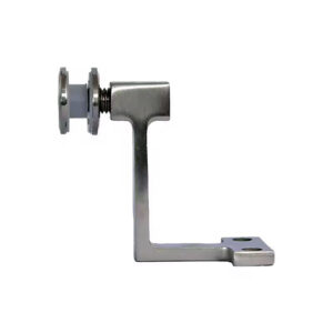
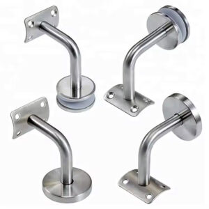
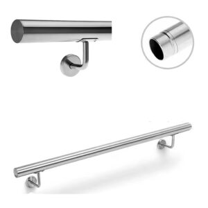
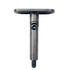
The practical implication is that the bracket specification should follow the wall condition map, not precede it. Before finalizing the bracket family, identify every distinct substrate type in the project and confirm that the proposed bracket—or bracket combination—handles the projection and anchoring requirements at each one. Where conditions vary significantly, specifying a second bracket variant is not a complication; it is the decision that prevents rework. Adjustable Wall Handrail Brackets address some of this variation by allowing projection adjustment within a single bracket form, which can reduce the number of distinct families needed while still accommodating substrate differences. The failure pattern to avoid is treating the bracket as a cosmetic element that can be resolved from a single catalog default and expecting it to perform correctly across genuinely different conditions.
The underlying logic of bracket selection is that four variables—substrate type, projection distance, expected point load, and accessibility geometry—interact with each other and must be resolved together before any aesthetic decision is made. A bracket that clears the visual review at specification can still produce a structurally inadequate, accessibility non-compliant, or rework-prone installation if those four variables were not checked against each other in the right sequence.
Before finalizing any bracket specification, confirm the substrate at every section of the run, calculate the effective projection including all finish and pack-out layers, verify that the resulting rail position satisfies clearance requirements, and check that the bracket material and anchor pattern can carry the load at the specified spacing. If any of those checks forces a change to the bracket family, that change is significantly cheaper to make at specification than at installation or post-occupancy audit.
Frequently Asked Questions
Q: What if the wall condition across the project run hasn’t been fully mapped before procurement closes?
A: Delay finalizing the bracket specification until every distinct substrate type is identified—not just the dominant one. Specifying from a single catalog default before the wall condition map is complete is the primary driver of mixed-quality installations, where some brackets anchor correctly and others underperform in ways that only become detectable under load or at a compliance review. A brief substrate audit at each section of the run is significantly cheaper than opening finished walls to reposition or replace hardware after handover.
Q: After confirming bracket type, projection, and substrate for each run section, what should happen before fabrication is released?
A: Run the full geometric check in sequence: actual wall face dimension, plus any finish or pack-out layers, plus the bracket projection as installed, confirmed against both the structural anchoring requirement and the accessibility clearance envelope. This check should happen as a single coordinated step—not as a structural review followed later by a separate accessibility review—because a change forced by one finding will affect the other. Releasing fabrication before this combined verification is complete is the point at which bracket-change costs become unavoidable.
Q: Does the 48-inch spacing threshold still apply when the bracket family is rated for higher point loads?
A: Higher bracket load ratings do not substitute for spacing discipline. The 48-inch threshold governs rail deflection between anchor points, not bracket capacity at a single point. A high-capacity bracket installed at excessive spacing still allows the rail tube to carry load in the unsupported span between anchors, which shifts the failure mode from the bracket connection to the rail itself. Spacing and bracket count must be planned against the full run geometry, and conservative spacing remains the correct approach on heavy-use commercial stairs regardless of individual bracket rating.
Q: When should adjustable wall handrail brackets be chosen over fixed-projection brackets, and where does that trade-off break down?
A: Adjustable brackets are the stronger choice when a project involves multiple substrate types or finish thicknesses that would otherwise require two or more distinct fixed-projection bracket families. The ability to tune projection within a single bracket form reduces SKU complexity and limits installer error at mixed-condition sections. The trade-off breaks down when the required projection range exceeds what the adjustable mechanism accommodates, or when the load path at maximum extension is not rated for the expected point load—particularly on heavy-use commercial stairs where lateral loading is directional and repeated. Confirm the rated capacity at the specific projection you need, not just at nominal extension.
Q: Is a bracket specification developed for a prior project on similar-looking wall conditions safe to carry forward without re-verification?
A: No. Carrying forward a prior specification without re-verification is the condition most likely to produce an anchoring failure that is invisible at handover. Wall conditions that appear similar can differ in substrate depth, finish buildup, and framing density in ways that change effective anchor engagement and projection distance. ASTM E894-88(2004) is explicit that anchorage performance is a function of actual substrate conditions, not hardware specification alone. Each project run requires its own substrate confirmation and projection calculation before the prior bracket family can be considered validated for reuse.