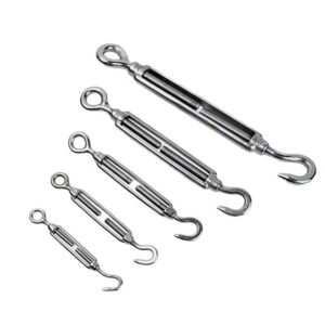
Can a cable tensioner be tightened, inspected, and locked off after every rail, post, and infill component around it is installed? That question has to be answered before post holes are drilled or cable lengths are cut, because once the surrounding assembly is in place, the tensioner’s tool access is fixed by geometry that drawings alone do not always reveal.
Access Zones Around the Installed Tensioner
A tensioner is not serviceable because it exists in the assembly; it is serviceable because a wrench, the installer’s hand, and a clear sightline can all reach it at the same time, in the same installed condition. This is a distinct requirement from fit. A tensioner can be dimensionally correct for the post, rail, and cable run and still be unreachable once the adjacent hardware is set, because fit describes whether the component occupies the correct space and access describes whether a tool can operate on it once that space is occupied.
The access zone around a tensioner is not a fixed clearance value; it changes with the tool the trade intends to use, the direction the tensioner must rotate to tighten, and the sequence in which surrounding parts go in. A tensioner positioned where a rail terminates, where an infill panel sits close against the post, or where trim or cladding will later close in the opening can lose access incrementally as each later trade completes its work. If the access path is checked only against the empty post or an isolated hardware photo, the reviewer is testing the wrong condition, because the relevant condition is the tensioner’s position inside the completed, as-built assembly.
This is why access has to be evaluated for the whole functional group, not the tensioner alone. A tensioner’s rotating body, its wrench flats, and its locking feature each need their own confirmed path, and that path depends on what sits next to the tensioner once rails, posts, and infill are all in place. Where the design places tensioners inside corner assemblies, near terminations, or close to fascia-mounted posts, this functional group includes whatever hardware governs that location, which is where poteau d'angle cable hardware and the broader termination assembly come into the access question rather than the tensioner body in isolation. Treating the tensioner as a standalone component when it is actually part of a termination detail is a common source of late-stage access problems, because the clearance that matters is the clearance left after the full detail is built, not the clearance implied by the tensioner’s own footprint.
Wrench Flats Rotation and Locking Features
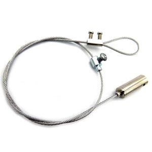
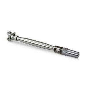
A tensioner’s serviceability depends on three distinct physical features remaining reachable, and each one fails independently of the others. The wrench flats need enough clear space for the intended wrench to seat fully and turn through its working arc. The body of the tensioner needs to rotate through the distance required to take up or release cable tension, which means the swept path of rotation, not just the static position of the fitting, has to stay clear. The locking feature, once the tension is set, needs a path for whatever tool or motion secures it, and that path is not necessarily the same path used for tightening.
Because these are three separate access requirements, a tensioner can pass a check on one feature and fail on another. A wrench might engage the flats cleanly while the body’s rotation arc is blocked by an adjacent post return, or the flats and rotation can both be clear while the locking feature sits against a surface that leaves no room for the tool that engages it. This is a meaningful distinction for project planning, because confirming “the wrench fits” is not the same as confirming the tensioner can be adjusted and locked off in its final position.
The practical consequence is that every one of these features has to be checked against the finished condition of the assembly, not an intermediate one. A tensioner installed before adjacent rail sections or infill is present may rotate freely and lock without resistance, then lose that access once later components close in around it. Where the installation sequence places the tensioner early relative to adjacent trades, the access check performed at that stage does not represent the access condition the installer will face when tensioning actually occurs. The sequence in which components go in, not only their final positions, determines whether the features stay reachable, which is why the access question has to be revisited at the point in the sequence closest to actual tensioning.
Corner Wall and Fascia-Mount Obstructions
Certain post and mounting conditions concentrate tool-access problems more than a straight run of infill does, because they combine a tight geometric envelope with hardware that must also satisfy a structural or termination role. Corner posts, wall-return conditions, and fascia-mounted posts share this characteristic: the same surfaces that make the connection structurally sound also tend to close off the space a wrench or hand needs to operate in.
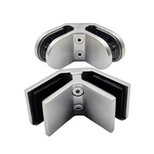
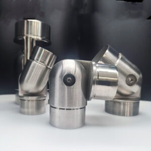
A corner condition narrows the angle available for a tool to approach the tensioner, and the hardware intended to manage that corner, such as corner post cable hardware, has to be evaluated for both its structural role and its effect on the remaining tool path. A wall-return condition removes an entire side of clearance that a freestanding post would otherwise offer, so the tensioner’s accessible arc is reduced to whatever remains on the open sides. A fascia-mounted post changes the orientation of the whole assembly relative to the tool, since the mounting surface itself occupies space that a top- or side-mounted post would leave open, and the direction a wrench needs to approach from may no longer be available at all.
What connects these three conditions is that the obstruction exists independently of whether the tensioner fits the drawing dimensionally. A tensioner specified for a corner post, a wall-return post, or a fascia-mounted post can be entirely correct for the span, the cable size, and the structural load path, and still leave no usable tool access once that specific mounting condition is built. This means the mounting condition itself needs a tool-access review distinct from its structural review, because the two reviews test different things: one tests whether the post and hardware carry the intended load, and the other tests whether anyone can actually adjust the tensioner once that post is standing.
Mockup Checks With the Intended Tools
| Mockup check | Condition to confirm |
|---|---|
| Wrench-flat access | The intended wrench can engage the flats after every adjacent component is installed. |
| Body rotation | The tensioner body can rotate in the intended tightening direction without the tool path being blocked. |
| Locking-feature access | The locking feature remains reachable after posts, rails, infill, and adjacent finishes are in place. |
| Terminal seating | The installer can observe terminal seating during the check. |
| Opposing fitting | The installer can hold the opposing fitting while tightening the connection. |
A drawing review and a dimensional check confirm that the tensioner belongs in the assembly; they do not confirm that it can be operated once the assembly is built. The only way to close that gap is to test the proposed detail physically, using the actual tool the installer intends to use, turning in the actual direction the tensioner requires for tightening, with the adjacent components in their installed positions or a representative equivalent of them.
This distinction matters because a tool substituted for the mockup, or a rotation direction tested in reverse of the actual tightening motion, can pass a check that the real installation condition would fail. The intended wrench may have a handle length or head profile that behaves differently near an obstruction than a generic tool would. The tightening direction matters because clearance that exists for loosening motion does not guarantee the same clearance exists for the tightening motion, particularly where the obstruction sits asymmetrically around the tensioner.
Two conditions beyond tool and rotation access also belong in this mockup: whether the installer can observe the terminal seating as the cable draws into final position, and whether the installer can hold the opposing fitting steady while applying torque to the tensioner. Both depend on sightlines and hand positions that a dimensional check does not evaluate, since a clear wrench path does not guarantee a clear sightline to the terminal, and a clear sightline does not guarantee there is room to brace the opposing fitting with a second hand or tool.
Running this mockup before post holes are drilled or cable lengths are prefabricated is what makes the check useful, because once holes are set and cable is cut to length, the geometry the mockup would have tested is already fixed in the field. A mockup performed after that point can only confirm a problem, not prevent one. Where the project allows a physical or representative mockup of the connection detail, including the surrounding hardware drawn from the relevant tensioner or corner hardware line, that mockup is the step that converts a drawing-level assumption about access into a field-confirmed one.
Drawing Changes Before Cable Fabrication
The decision point this creates is direct: if the mockup shows that the installer cannot observe terminal seating, or cannot hold the opposing fitting while tightening, the connection detail needs to change before tensioning begins, not after. These two conditions are treated as trigger points rather than preferences because they describe whether the installer can confirm the connection is correctly made at all, independent of whether the tensioner itself has enough clearance to turn.
A detail that fails on tool or rotation clearance alone may sometimes be corrected by a different tensioner orientation, a revised post detail, or a change in which side of the assembly carries the adjustable connection. A detail that fails on observation or on holding the opposing fitting is a different kind of failure, because it means the installer cannot verify the connection was made correctly even if the tool technically reaches the hardware. Design review channels, including the questions raised in corner post and termination hardware planning, exist precisely to catch this before shop drawings are finalized, since a change at that stage affects drawings rather than fabricated material.
The reason this has to happen before cable fabrication, specifically, is that cable lengths and post hole locations are two of the few elements in a cable railing assembly that are difficult to adjust once committed. A drawing change costs a revision; a fabricated cable or a drilled post commits the geometry the mockup just showed to be unworkable. Where the project team supplies the confirmed access findings, rotation direction, and mockup results to the hardware supplier during quotation or configuration review, that information becomes part of what determines which tensioner configuration, orientation, or corner hardware pairing is actually ordered, rather than defaulting to a configuration selected before the access condition was tested in the field.
Questions fréquemment posées
Q : When should cable tensioner tool access be verified?
A : Verify it before releasing post holes or prefabricated cable lengths. Test the proposed detail with the intended tools and tightening direction after accounting for posts, rails, infill, and adjacent finishes.
Q : Is it enough for the tensioner to fit within the drawing clearance?
A : No. A fitting may fit the space while a corner, wall return, fascia-mounted post, or closely spaced infill blocks wrench engagement or body rotation. A physical mockup should confirm the complete tool path.
Q : What project information should be included in the access review?
A : Identify the intended wrench, tightening direction, installation sequence, and final position of adjacent components. The review should also confirm that the installer can see terminal seating and hold the opposing fitting during tightening.
Q : What should happen if the locking feature or opposing fitting cannot be reached?
A : Change the connection detail before cable fabrication or tensioning begins. The revised detail should preserve access to the locking feature and allow the opposing fitting to be held in the completed assembly.