Herrajes y montaje de postes

Herrajes y montaje de postes
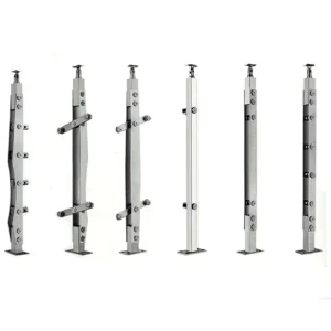
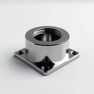
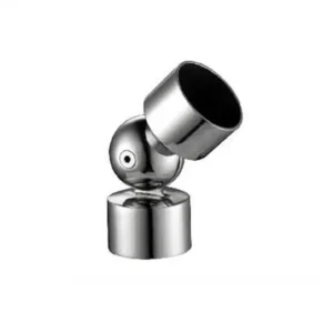
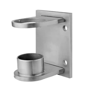
Choose post hardware from the real mounting condition. A base fixed on top of a surface, a side-mounted fascia plate, an adjustable interface and a core-mounted post create different geometry, installation access and site responsibilities. Caps and covers finish visible openings but do not replace structural fixing components. This category routes those tasks separately.
Discuss mounting hardware on WhatsApp
Current hardware routes
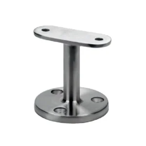
Placas base de montaje en superficie
Use where posts are fixed on top of a prepared supporting surface. Show the finished build-up, base position, anchor responsibility and cover requirement.
Placas de base para montaje en el salpicadero
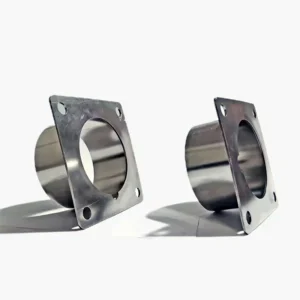
Use for side-mounted posts. Provide the structural face, post offset, access behind the fixing, edge geometry and alignment target.
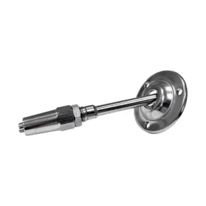
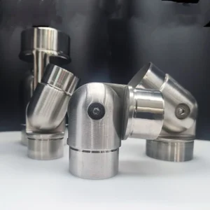
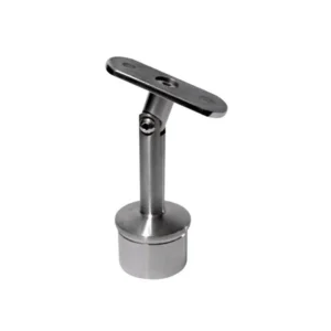
Use when a defined adjustment is required for installation. State the adjustment direction, required range and final locking/cover condition.
Placas de base de alta resistencia
Use only when the project has a defined demand for a more substantial base detail. The title is not a load rating; submit design loads and substrate information for review.
Sistemas de base con fijación central
Use for posts installed into prepared openings. Coordinate hole geometry, embedment, drainage/waterproofing, fixing material and installation sequence.
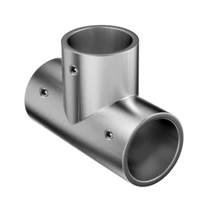
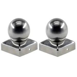
Use for visible tube ends and post tops. Match the receiving profile, exposed edge, cap form, finish and intended retention method.
Representative fixing and finishing parts
Structural fixing is not the same as visible finishing
Component — Primary job — Must be matched to
Base plate or mounting body — Transfers the post connection to a defined support. — Post profile, design action, substrate, edge geometry, anchors and installation access.
Cover or trim — Conceals or finishes a visible interface. — Base footprint, post shape, finished floor level, removability and finish.
Post or end cap — Finishes an open tube or post top. — Outside/inside receiving profile, edge condition, retention method and visible form.
Do not treat a cover as the structural base or infer that fasteners shown beside a product are suitable for the project substrate. The quotation should identify what is included, while the project designer or engineer defines the required installed capacity and anchor design.
Choose the mounting route from site constraints
• Surface mount: record the structural surface beneath finishes, edge distance, level tolerance, water path and whether the base remains accessible.
• Fascia mount: record the side structure, bolt access, post offset, finish build-up and how repeated posts will be aligned.
• Adjustable base: state exactly what must move – height, angle, rotation or plumb – and how the final position is locked and covered.
• Core mount: coordinate the prepared opening, post insertion, temporary support, fixing/grouting sequence, drainage and waterproofing.
• More substantial base detail: provide design actions and substrate information. “Heavy duty” is a product route, not evidence of a universal capacity.
Inquiry package and quotation checks
A photo of the mounting area plus a section sketch is often enough to start. Add the post profile, base elevation, substrate description, available edge distance, access, exposure, finish and estimated quantity.
Ask the proposal to state:
• mounting body or plate geometry and its post interface;
• cover, cap or trim pieces included;
• loose fasteners or anchors included, proposed or excluded;
• material grade and finish proposed for each visible part;
• adjustment direction and locking detail where relevant;
• site drilling, grouting, welding, waterproofing and finishing responsibilities;
• drawings, design actions and substrate data still needed before production.
Related Posts:
What Should Be Included at Handrail Ends: Returns, End Caps or Open Coordination Points?
Distinguish handrail returns, end caps and unresolved end interfaces, then schedule each termination by function, adjoining construction and supply responsibility.
Factory-Cut or Site-Trimmed Handrails: Which Release Method Fits the Available Dimensions?
Choose factory-cut or site-trimmed handrails by checking dimension status, datums, mating allowances and the finish work attached to each cut.
¿Solo el tubo del pasamanos o un paquete completo de componentes? ¿Qué debe incluir el presupuesto del proveedor?
Compara los presupuestos de barandillas que incluyen solo tubos y los que incluyen el paquete de componentes, desglosando los accesorios, la fabricación, los elementos de fijación, los acabados y las cantidades suministradas.
Suministro de barandillas continuas o por tramos: ¿qué estrategia de suministro se adapta mejor al transporte y al montaje in situ?
Compara el suministro de barandillas continuas y seccionales teniendo en cuenta el acceso para la entrega, la ubicación de las uniones, los detalles de acoplamiento y la identificación de las secciones antes de dar luz verde a la fabricación.
¿En qué punto de un recorrido mixto debe pasar una barandilla de estar apoyada en la pared a estar apoyada en un poste?
Elige un cambio en el soporte del pasamanos comparando las uniones entre la pared y el poste, manteniendo la trayectoria de sujeción y situando la transición en los planos coordinados.
Paneles de malla planos, inclinados o con transición de plano a inclinado: ¿qué geometría corresponde a cada tramo de barandilla?
Elige entre la geometría de paneles de malla «nivelada», «inclinada» o «de inclinada a nivelada» en función del tramo de barandilla, la orientación del patrón, las interfaces y los planos del proyecto.
Proyectos de Esang

Certificado de Esang
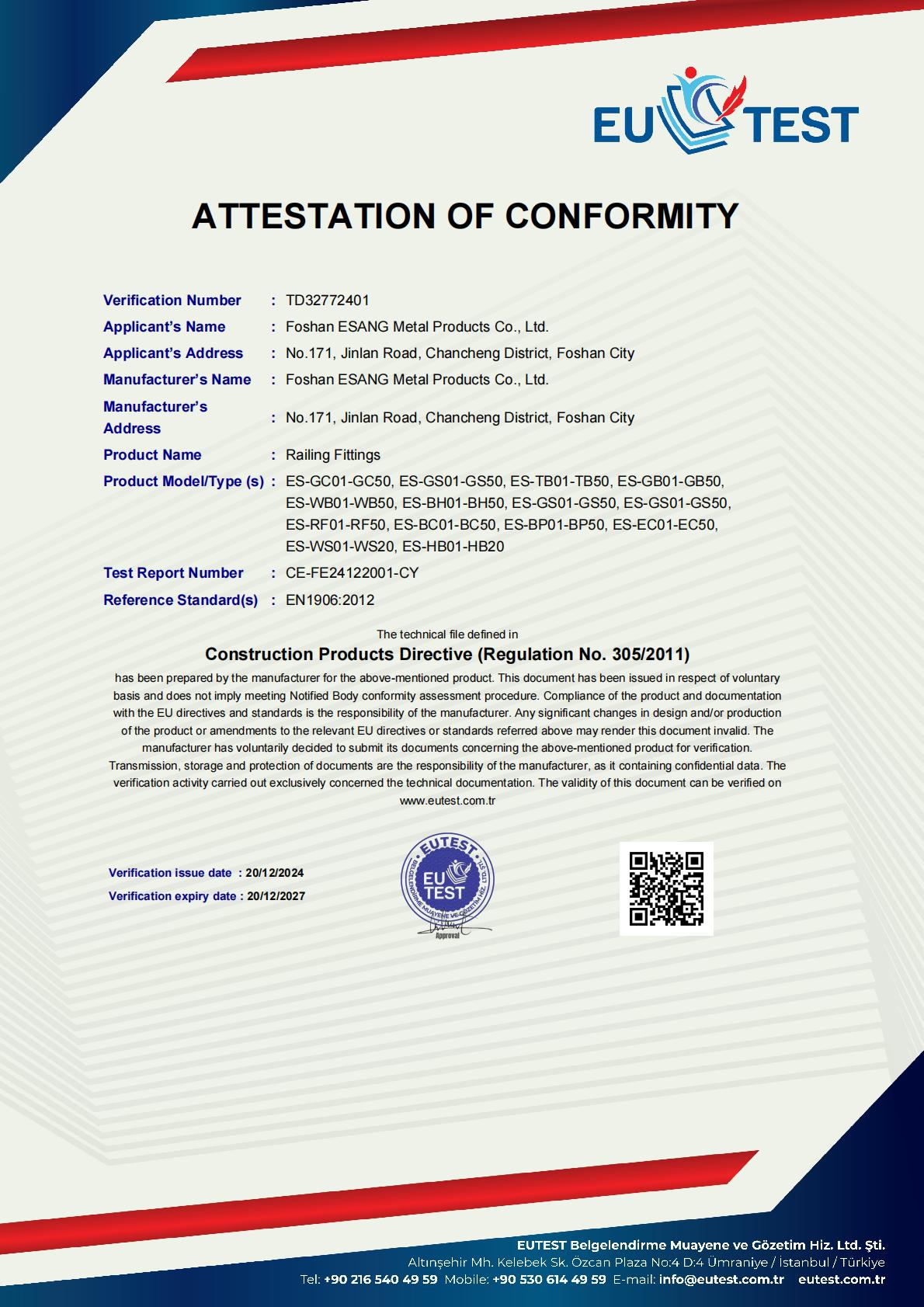
Foshan ESANG Metal Products se enorgullece de mantener Certificación CE (Verificación n.º TD32772401) en virtud de la Directiva sobre productos de construcción (Reglamento n.º 305/2011), lo que afirma nuestro compromiso con los más altos estándares europeos de seguridad y calidad.
Gama de productos certificados:
Nuestra amplia gama de herrajes para barandillas, que incluye abrazaderas de vidrio, tensores, soportes, soportes de pared, zapatas, herrajes para pasamanos, herrajes para cables y componentes para postes, satisface los requisitos más exigentes. EN1906:2012 garantizando la integridad estructural y la fiabilidad del rendimiento en todas las instalaciones.
Qué significa esto para su proyecto:
✓ Cumplimiento total de la normativa para los mercados europeos e internacionales
✓ Rendimiento de seguridad y durabilidad verificado de forma independiente.
✓ Soporte de documentación para las especificaciones arquitectónicas
✓ Tranquilidad gracias a la garantía de calidad de terceros
Certificación válida hasta 2027 | Informe de pruebas: CE-FE24122001-CY
Proyectos de Esang

Productos de referencia