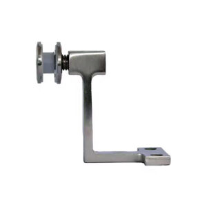
A cable tensioner that fails to hold tension, cracks at the body, or seizes mid-adjustment raises a question that goes beyond buying a matching part: does the replacement fit the installed assembly, or does it only resemble it? Getting this wrong on a cable railing run can leave the system under-tensioned, misaligned, or dependent on a connection the new part was never built to make.
Installed Data Needed for a Replacement Match
| Installed assembly element | Data needed before replacement selection |
|---|---|
| الكابل | Diameter and construction |
| Cable terminal | Terminal method |
| Threaded connection | Thread size and thread hand |
| Tensioner body | Body travel and material |
| ما بعد الاتصال | واجهة النشر |
Before any replacement is selected, the installed assembly has to be read correctly, not assumed from the tensioner’s outward appearance. A tensioner is one element in a chain that includes the cable itself, its terminal, a threaded connection, and a post interface, and each of these can vary independently of what the tensioner body looks like.
Cable diameter and construction matter because the tensioner’s internal bore, swaging profile, or gripping mechanism is sized and shaped for a specific cable type. A tensioner built for one cable construction can appear to accept a different cable of similar diameter, but the internal fit, grip, or seating may not hold tension correctly even if the parts physically go together.
إن terminal method on the installed cable end changes what kind of tensioner can connect to it at all. Where the cable terminates in a swaged fitting, the replacement tensioner must interface with that fitting’s geometry. Where the system uses a swageless or field-attachable terminal, the replacement must match that mechanism instead. Confusing the two terminal methods risks a connection that threads or seats without actually transferring load the way the original assembly did.
Thread size and thread hand on the tensioner’s adjustment screw determine whether the new part can even engage the opposing hardware. A tensioner with the correct outward dimensions but the wrong thread pitch or the opposite hand will not draw tension correctly, or will not engage at all, even though it may appear to thread partway.
Body travel, meaning how much adjustment range the tensioner provides, sets whether the replacement can take up the same range of slack and tension as the original. A shorter-travel body installed where the run needs more adjustment leaves the system unable to reach proper tension even if every other interface matches.
Tensioner body material has to be confirmed against the project’s finish and corrosion environment, since a visually similar body may be a different stainless grade or finish than what the original specification called for.
Finally, the post interface, the point where the tensioner connects to the post or structural anchor, must match the installed hole pattern, fitting type, or mounting method. Recording these elements before sourcing a replacement is what allows a supplier or fabricator to confirm compatibility rather than guess from a photograph.
Damage Causes Beyond the Tensioner Body
A cracked, seized, or loosened tensioner is often the visible symptom rather than the complete explanation. Before ordering a replacement, the cable end, the opposing terminal, the post hole, and the general access condition around the tensioner deserve inspection, because any of these can have contributed to or resulted from the same event that damaged the tensioner.
Overload changes the picture when the tensioner shows deformation consistent with a force beyond its adjustment range, in which case the cable, the opposing terminal, and the post connection may have absorbed related stress even if they still appear intact. Replacing only the tensioner in that situation leaves the question of whether the rest of the run was also affected unanswered.
Misalignment is a different mechanism: if the post hole or the terminal seating was not aligned with the tensioner’s axis, the tensioner can wear or bind asymmetrically, and a replacement installed into the same misaligned geometry will develop the same condition again regardless of how well it matches the original part.
Corrosion changes the inspection priority toward the cable end and the post interface, since a tensioner that has corroded in a particular environment may indicate that the adjoining hardware in that same environment is also degraded, even where it has not yet failed visibly.
Tool damage during a prior adjustment or removal attempt is a mechanical cause distinct from load or environment: marks on the post hole, a rounded adjustment feature, or a deformed terminal can result from the tool used rather than from the tensioner’s service life. Where this is the case, the access condition around the fitting also matters, since tool damage can indicate that the original access method was constrained and that any replacement procedure needs a different approach.
Treating the tensioner as the only damaged component skips this inspection step and risks installing a correctly matched replacement into a connection that still carries the original problem.
Cable Terminal Thread and Post Compatibility
Thread and post compatibility is where a replacement tensioner either completes the assembly correctly or introduces a connection that only appears sound. The thread size and hand on the tensioner must match the opposing threaded hardware exactly; a near match can engage for several turns before binding or stripping, which can be mistaken for a tightening tensioner rather than a mismatched one.
The cable terminal and the tensioner’s receiving end form a second interface that depends on terminal method rather than overall size. A tensioner designed to pair with threaded cable end fittings will not necessarily substitute correctly for one designed around a different terminal mechanism, even where both are described as compatible with the same cable diameter.
The post interface is the third point of compatibility, and it depends on how the original installation anchored the tensioner, whether through a drilled hole, a surface mount, or another post connection method. Where the post hole was sized or shaped for one tensioner’s mounting hardware, a replacement with a different mounting profile may not seat the same way even if its body dimensions are otherwise similar.
Each of these three interfaces can be correct in isolation while the complete connection still fails, which is why confirming them together, rather than confirming the tensioner body alone, is what establishes whether the replacement will function as part of the run.
Substitution Evidence for the Named Assembly
| Evidence or observation | Decision use | Limit |
|---|---|---|
| Physical similarity to the installed fitting | Treat the proposed fitting as unconfirmed | Similarity alone does not confirm named assembly compatibility or the required installation method |
| Named assembly compatibility confirmation | Confirm whether the proposed fitting is compatible with the named assembly | Required installation method still needs confirmation |
| Required installation method confirmation | Confirm how the proposed fitting must be installed | Named assembly compatibility still needs confirmation |
| ISO 2408:2017 | Check requirements for steel wire ropes within the standard’s stated product scope | Does not establish replacement-terminal compatibility or cable-railing system compliance |
| ISO 3506-1:2020 | Check mechanical and physical property classes for covered stainless bolts, screws, and studs at ambient temperature, after verifying that the fitting is within scope | Torque, fatigue, shear, and joint performance need separate evidence |
A tensioner that looks like the one being replaced is not, on that basis alone, a confirmed substitute. Visual similarity describes outward shape and finish; it does not confirm that the replacement is compatible with the named assembly or that it can be installed using the same method as the original. Treating a similar-looking fitting as interchangeable before that confirmation shifts risk onto the installed system rather than resolving it before replacement.
Two separate confirmations are needed, and neither substitutes for the other. The first is whether the proposed fitting is compatible with the named assembly, meaning that the specific cable tensioner system or swageless cable tensioner design matches the installed cable, terminal, thread, and post interface already identified. The second is the required installation method for that fitting, since a compatible component installed with the wrong method, such as an incorrect swaging approach where a swageless connection was intended, can fail to perform correctly even where the hardware itself was the right choice.
Published standards can inform parts of this evidence but do not close the compatibility question on their own. ISO 2408:2017 sets requirements for steel wire ropes within its stated product scope, which can support confirming that the installed or replacement cable meets a wire rope requirement, but it does not establish replacement-terminal compatibility or cable-railing system compliance. ISO 3506-1:2020 sets mechanical and physical property classes for corrosion-resistant stainless fasteners such as bolts, screws, and studs at ambient temperature; it can support confirming that a threaded fastener used in the tensioner connection falls within a stated property class, but only after confirming the fastener is within that standard’s scope, and it does not address torque, fatigue, shear, or joint performance, which need separate evidence.
Where a buyer provides the installed assembly details gathered earlier, that information is what allows a supplier’s configuration or quotation review to confirm whether a specific cable tensioner system or threaded cable end fitting matches the named assembly, rather than leaving that confirmation to visual comparison.
Retensioning and Frame Checks After Replacement
Installing a confirmed replacement does not complete the task until the related cable run has been retensioned and the surrounding connections rechecked. Retensioning should follow the system instructions for the specific cable tensioner system or swageless cable tensioner installed, since tensioning sequence and method can differ between tensioner designs even where the end result looks the same.
After retensioning, terminal seating needs a direct check: the cable terminal, whether swaged or threaded, should be seated fully against its mating surface, since a terminal that appears connected but is not fully seated can hold initial tension and then shift under load or thermal movement.
Frame alignment is the next check, because a replacement tensioner installed under tension can reveal misalignment that was not apparent before the run was tightened. Where the post or frame has shifted or was never perfectly aligned, tensioning the cable can expose that condition through uneven cable angle or visible strain at the post interface, which may indicate that the post connection itself needs attention beyond the tensioner.
Locking the tensioner in its final position is a distinct step from reaching correct tension, since a tensioner that is correctly tensioned but not locked can loosen under vibration or repeated use. Confirming the locking mechanism is engaged, rather than assuming tension alone holds the assembly, closes that gap.
Finally, remaining adjustment travel should be checked against the tensioner’s range, since a replacement installed near the end of its travel leaves little margin for future retensioning as the cable settles or the system experiences normal use. Where travel remaining is minimal immediately after installation, that condition is worth resolving before considering the replacement complete, since it limits the ability to retension the run later without replacing the tensioner again.
الأسئلة الشائعة
س: Can I replace only the damaged tensioner?
A: Only after checking whether the damage extends beyond the tensioner. Inspect the cable end, opposing terminal, post hole, and access condition for signs of overload, misalignment, corrosion, or tool damage that could affect the wider assembly.
س: What should be identified before the damaged tensioner is removed?
A: Record the installed cable diameter and construction, terminal method, thread size and hand, tensioner body travel and material, and post interface. These details form the basis for checking a replacement against the installed assembly.
س: Is a similar-looking tensioner an acceptable replacement?
A: Visual similarity is not enough. Confirm compatibility with the named assembly and verify the required installation method before substituting the fitting.
س: Do ISO 2408:2017 or ISO 3506-1:2020 prove that a replacement is compatible?
A: No. ISO 2408:2017 addresses steel wire ropes within its stated scope, while ISO 3506-1:2020 covers property classes for certain stainless fasteners at ambient temperature. Neither alone establishes replacement-terminal compatibility, installation requirements, or cable-railing system compliance.
س: Is the replacement complete once the new tensioner is installed?
A: No. Retension the related run under the system instructions, then recheck terminal seating, frame alignment, locking, and remaining adjustment travel before treating the work as complete.