A hardware submittal rejected at the engineering review stage rarely fails because the glass or fitting was wrong. It fails because the load claim arrived without the substrate assumptions, anchor type, or installation conditions that would let an engineer confirm the numbers apply to the actual project. That gap — between a supplier’s tested assembly and the site conditions on record — is the most common trigger for procurement rework and schedule slippage in glass railing projects. Recovering from it means going back to the supplier for data that should have been part of the initial request. The judgment that matters is not whether a product has a load figure attached to it, but whether that load figure is traceable to an assembly that matches your project conditions.
Load claims must cover the complete installed assembly
A load value printed on a product data sheet does not describe a system. It describes a result obtained under a specific combination of glass thickness, fitting type, fastener grade, anchor product, embedment depth, substrate condition, and installation sequence. Change any one of those variables and the claim no longer necessarily holds. That distinction matters because hardware buyers frequently receive product data that reports a load figure in pounds per linear foot without identifying the conditions under which it was measured.
Wind load is a useful illustration of where incomplete claims create exposure. The actual lateral demand on a glass railing varies with building height, exposure category, and regional climate. A load claim that does not identify the wind load case it was derived from, or the mounting geometry assumed in the test, cannot be confirmed as adequate for a given site without additional engineering work. The risk is not that the product is defective; the risk is that the tested condition does not match the project condition, and no one catches it until the submittal is reviewed.
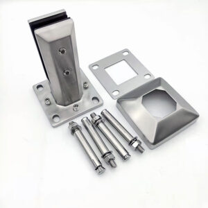
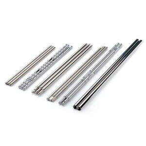
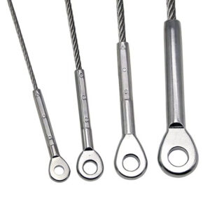
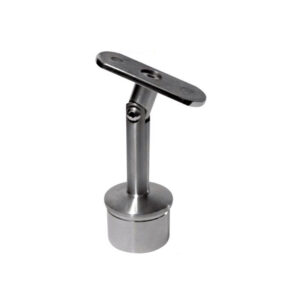
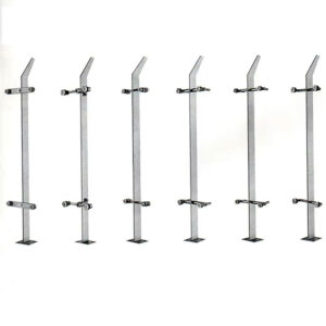
The complete chain that a load claim must describe runs from the glass panel through the fitting, through the fastener, through the anchor, and into the substrate. A break anywhere in that chain can undermine performance even when the glass and fittings individually meet specification. Buyers who request a load figure without requesting the chain description are accepting a partial answer as a complete one.
Glass, fitting, fastener, anchor and substrate chain
The practical consequence of treating a load claim as a single-variable statement is that installation failures — not material defects — account for most in-service problems with glass railing assemblies. Improper mounting hardware, inadequate anchoring, and thermal expansion neglect each represent a point in the chain where load transfer breaks down regardless of whether the glass or fitting met its specification. That pattern matters for procurement because it shifts the review focus from product quality alone to the completeness of the assembly documentation.
Thermal expansion is the element most frequently treated as a detail when it is actually a structural risk. An assembly that does not accommodate the temperature range of the project site can stress the glass, loosen fittings, or progressively detach anchors through cyclic loading. A supplier whose load claim does not address expansion accommodation for the expected temperature range is providing data that describes a static test condition, not long-term assembly behavior.
The table below maps each chain element to its failure risk and the confirmation each requires.
| Chain Element | Typical Failure Risk | ما الذي يجب تأكيده |
|---|---|---|
| Anchor & substrate | Anchorage pull-out or concrete breakout if anchor type, embedment depth, or substrate condition differ from the tested setup | Load claim explicitly states assumed concrete type, embedment depth, and surface condition (cracked/uncracked, flatness) |
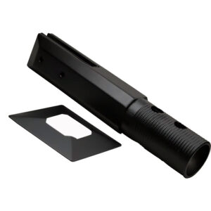
| Fasteners & mounting hardware | Loose or improperly installed hardware disrupts the load path, even when components meet specification | Supplier installation instructions provide specific torque values, hardware grade, and assembly sequence |
| التمدد الحراري | Ignored expansion can stress the glass, loosen fittings, or detach anchors | Assembly design includes expansion accommodation (joints, flexible connections) for the project temperature range |
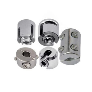
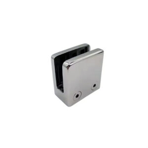
Anchor and substrate together carry the highest consequence if assumptions go unstated. Anchorage performance in concrete changes with concrete type, crack condition, and embedment depth. A supplier who declares a load figure without specifying those conditions is implicitly asking the buyer to assume the site matches the tested setup — an assumption that often does not survive engineering review. For projects using قضبان قاعدية زجاجية هيكلية, confirming that the anchor spacing and substrate condition in the product data match project conditions is a prerequisite before any submittal is prepared.
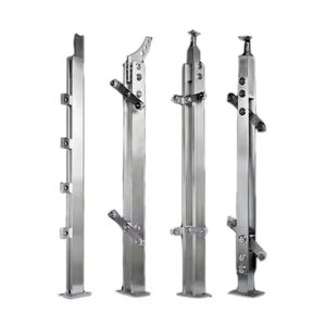
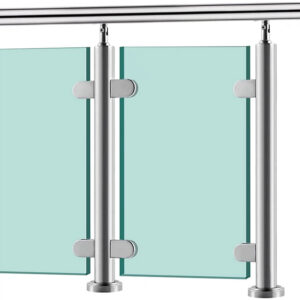
Point support versus continuous channel evidence
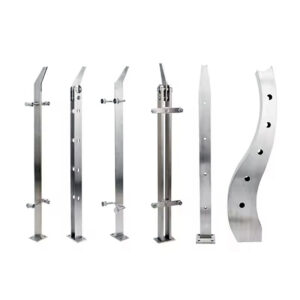
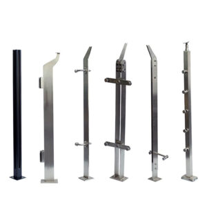
The type of anchorage evidence a supplier needs to provide depends on the mounting geometry, and buyers who apply the same review standard to point-fixed and continuous channel systems are likely to accept insufficient data for one or both. The distinction is not regulatory classification; it is a difference in how load is distributed and therefore what failure mode is most probable.
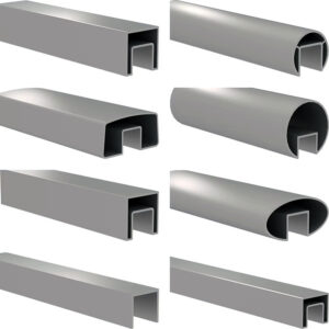
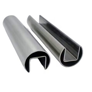
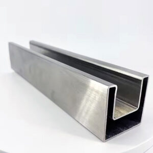
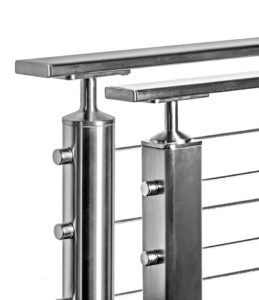
Continuous systems — base shoe and U-channel — distribute lateral load along the full length of the channel. That distribution reduces peak demand at any single anchor point, but it introduces sensitivity to anchor spacing and substrate flatness that product-level data rarely addresses. A continuous channel installed over a substrate with significant deviation in flatness may not engage anchors uniformly, reducing effective distribution and concentrating load in a pattern the tested assembly did not replicate.
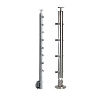
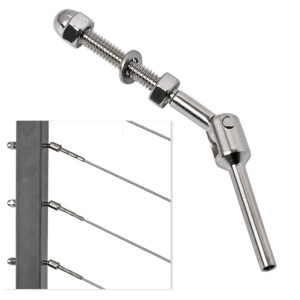
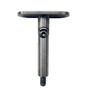
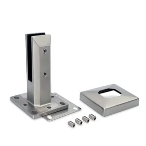
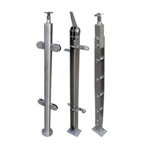
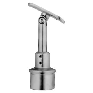
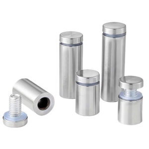
Point-fixed systems, including صنابير زجاجية مخصصة للاستخدام المكثف and spider fittings, concentrate the full moment and shear demand at discrete anchor locations. Each anchor must carry what a continuous system would spread across multiple points. That means localized pull-out and shear evidence for each anchor position is not optional — it is the primary proof of capacity. A load claim expressed in plf for a spigot system without identifying the spacing assumption and per-anchor demand is not usable for engineering review without recalculation.
| نظام التركيب | Load Strength Contribution | Anchorage Evidence Requirements |
|---|---|---|
| Base shoe | عالية جداً | Distributed load along channel; evidence must cover anchor spacing and substrate flatness |
| U-channel | عالية | Similar to base shoe; continuous embedment distributes load, requiring verified anchor spacing |
| Spider fittings | High (localized) | Point loads concentrate force; need strong pull-out and shear evidence for each anchor point |
| Spigot mounts | متوسط إلى مرتفع | Localised moment and shear; anchor capacity evidence must reflect isolated point support |
The downstream consequence of mismatched evidence is that an engineer reviewing a submittal for a point-fixed system may accept the system-level plf figure and miss that no localized anchor capacity data was provided. That omission typically surfaces during permit review or third-party inspection, not during procurement — which is why it is a procurement problem that buyers must close before submittal, not after.
Supplier data gaps in project-specific anchorage
The friction point in most glass railing procurements is not that suppliers provide false data. It is that suppliers provide real data from a tested assembly while omitting the conditions that defined that assembly. Substrate condition, anchor selection, and installation method assumptions are the three gaps that appear most consistently in standard product documentation, and each one can cause engineering rejection when site conditions differ from the unstated baseline. For a detailed breakdown of what those gaps look like and what questions to use against them, this overview of stainless steel glass railing load testing covers the tested assembly context in more depth.
The installation method gap is the one most likely to be treated as a quality-control matter rather than a load-claim matter. When a supplier’s load statement assumes controlled torque values, specific hardware grades, and a defined assembly sequence, a field deviation from any of those conditions can produce a load path that differs from the one tested. That failure mode is not traceable to material quality; it is traceable to incomplete documentation. Buyers who do not ask whether installation assumptions are documented cannot confirm that site practice matches the tested condition.
Each data gap listed in the table below represents a point where supplier documentation is technically accurate but practically incomplete for project-specific engineering confirmation.
| Data Gap | ما أهمية ذلك | What to Ask Supplier |
|---|---|---|
| Substrate condition not stated | Anchorage performance varies with concrete type, cracking, and embedment depth; missing data can mask mismatch with site conditions | What concrete type, crack condition, and embedment depth were assumed in the tested assembly? |
| Anchor selection not specified | The tested anchor product, size, and installation affect declared load values; changing anchor invalidates the claim | Which anchor product and size was used in testing, and is it compatible with the project substrate? |
| Installation method assumptions omitted | Load claims often assume controlled installation; field deviations in torque, alignment, or thermal detail cause failures unrelated to material quality | Does the load statement assume specific installation steps, and are those steps documented for site verification? |
The review implication is that each of these gaps should be treated as a procurement checklist item, not a post-submittal correction. Requesting this information before submittal preparation closes the loop before schedule pressure makes the request difficult to act on.
Acceptance condition for load and anchorage statements
A load and anchorage statement from a supplier is acceptable for engineering review when it identifies the tested or assumed assembly completely enough that an engineer can determine whether the project conditions match. That standard has a practical threshold: if the statement does not name the substrate type, anchor product, embedment depth, and installation method, it describes a result without describing the conditions required to reproduce it.
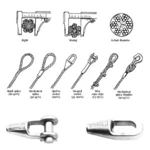
Testing frameworks such as ASTM E935-21 and ASTM E894-88 provide a reference for how load resistance is measured and reported — drop ball and human impact simulation, with results expressed in pounds per linear foot. Those methods are relevant context for understanding how a supplier’s figures were generated, but they do not by themselves confirm that the tested assembly matches the project. A load figure derived through a recognized method is still only as useful as the assembly description that accompanies it.
Applicable building codes require glass railing systems to meet load resistance thresholds equivalent to those for metal railing systems. Whether a supplier’s data satisfies those thresholds for a given project is a function of the match between tested conditions and site conditions, not just the numerical value. A figure that meets the threshold under the tested setup can fall short of meeting it under field conditions if the substrate is cracked concrete where uncracked was assumed, or if the anchor spacing exceeds what the tested layout used.
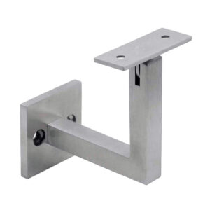
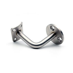
The acceptance decision, in practice, is binary: either the supplier has documented the assembly completely enough to allow that match assessment, or they have not. If they have not, the correct procurement action is to request the missing information before the submittal moves forward — not to accept the partial statement and rely on the engineer to identify the gaps. أقواس دعم الألواح الزجاجية and similar intermediate components carry the same documentation requirement: the load claim attached to any component must trace back to an assembly where that component’s contribution was tested under defined conditions.
The central procurement discipline in glass railing hardware is treating every load figure as an assembly result, not a product property. Before a submittal moves to engineering review, the data package should answer four questions: what substrate and anchor conditions were assumed in the tested assembly; what anchor product and spacing define the declared capacity; whether the installation method is documented to a level that supports field verification; and whether the tested geometry — point-fixed or continuous — matches the project. Missing answers to any of these questions do not make a product unsuitable. They make the claim unusable until the answers are supplied.
The additional confirmation that matters before procurement is finalized is whether the site conditions — substrate type, flatness, crack condition, exposure — were disclosed to the supplier before the load claim was issued. A claim generated without that input reflects a generic tested condition. One generated against project-specific conditions, or at minimum confirmed as applicable to them, is the standard worth holding suppliers to.
الأسئلة الشائعة
Q: What should a contractor do if the supplier cannot provide the tested substrate type and anchor product that support their load claim?
A: Treat the submission as incomplete and withhold it from engineering review until the missing information is supplied. A load figure without identified substrate and anchor conditions cannot be confirmed as applicable to the project site — accepting it and relying on the engineer to catch the gap typically results in rejection at permit review or third-party inspection, creating schedule delays that are harder to recover from than a delayed submittal.
Q: Does thermal expansion need to be addressed in the supplier’s load documentation, or is it handled separately during installation?
A: It must appear in the supplier’s assembly documentation, not be deferred to installation. An assembly that does not account for the project’s temperature range can progressively stress the glass, loosen fittings, or cycle anchors toward detachment — none of which is visible during initial inspection. A load claim derived from a static test condition does not describe long-term behavior unless expansion accommodation for the expected range is identified as part of the tested or assumed assembly.
Q: Is a load claim verified through ASTM E935-21 or ASTM E894-88 automatically acceptable for engineering submittal?
A: Not automatically. Those standards confirm how the figures were measured and reported, but they do not confirm that the tested assembly matches the project. A result derived through a recognized test method is still only valid for conditions that match the tested setup — cracked versus uncracked concrete, anchor spacing, embedment depth, and mounting geometry all determine whether the numerical threshold holds under field conditions.
Q: When does switching from a continuous channel to a point-fixed system change what anchorage evidence the supplier must provide?
A: It changes the evidence requirement significantly. Continuous systems distribute load along the channel length, so anchor spacing and substrate flatness govern capacity across the run. Point-fixed systems concentrate full moment and shear demand at each discrete anchor location, making per-anchor pull-out and shear data the primary proof of capacity — a system-level plf figure without the spacing assumption and localized anchor demand is not sufficient for engineering review of a point-fixed installation.
Q: If site conditions such as substrate flatness or crack condition were not disclosed to the supplier before the load claim was issued, is that claim still usable?
A: Only with additional confirmation. A claim generated without project-specific input reflects the generic tested condition, which may or may not match the site. Before procurement is finalized, the buyer should disclose actual site conditions to the supplier and obtain explicit confirmation that the declared capacity remains applicable — or request a revised claim generated against those conditions. Using a generic claim on a non-matching site is the scenario most likely to trigger engineering rejection after the submittal is already in motion.