Drilling into a concrete slab before anyone has confirmed reinforcement locations, edge distances, or the condition of any existing waterproofing membrane is one of the more reliable ways to generate expensive rework on a railing installation. A misplaced hole that clips rebar or falls short of minimum edge distance does not just mean re-drilling—it can mean a rejected anchor layout, a structural review, and a slab repair that delays the entire railing schedule. The decisions that prevent that outcome are not made at the drill; they are made earlier, when base plate geometry, slab data, and waterproofing responsibilities are resolved together. What follows gives contractors, architects, and procurement teams a clearer basis for those decisions before layout begins.
Slab Information Required Before Base Plate Layout
Base plate layout cannot be treated as a field task that begins when the installer arrives with a template. The slab conditions that govern where anchors can be placed—thickness, reinforcement depth and spacing, and any post-tensioning—need to be confirmed before the plate pattern is fixed. Without that information, the hole layout is essentially an assumption, and assumptions in concrete are corrected with grinding wheels and epoxy.
The practical inputs to request before layout include as-built rebar drawings or a GPR scan result, the slab thickness at the installation perimeter, any post-tensioning tendon locations, and the design-specified anchor embedment depth. Embedment depth matters because a shallow slab or a zone with dense reinforcement close to the surface may not accommodate the required anchor length, which changes the anchor selection and potentially the plate geometry. If embedment capacity cannot be confirmed through documentation, that gap should be resolved before layout proceeds—not treated as something the installer will discover at the drill.
ASTM E894 provides a testing framework for evaluating anchorage performance in permanent metal railing systems. It is a useful reference for understanding how installed anchors are expected to behave under load, but it does not function as a slab survey protocol. The slab data collection step is a design coordination requirement, not a test procedure. Teams that treat it as optional tend to encounter the anchor conflicts described in the next section.
Anchor Conflicts With Edges and Reinforcement
The two most common layout conflicts—anchor too close to a slab edge, or anchor positioned over a rebar—are predictable and preventable when slab data is in hand before drilling. They become rework when that data is skipped.
Edge distance requirements for concrete anchors are structural requirements drawn from codes such as ACI 318, not parameters that can be estimated by eye. A post located near a deck perimeter, stair edge, or expansion joint will have at least one anchor near a concrete edge, and depending on the plate pattern, possibly more. If the plate layout has not been checked against actual edge conditions, there is a real chance that one or more holes will fall within a reduced-capacity zone. The consequence is not just a hole that needs to be abandoned—it is a layout that may need to be redesigned, which means the plate, the post centerline, and potentially the rail alignment all shift.
Reinforcement conflicts create a different problem. Drilling into rebar damages the bar and the drill, and the resulting void cannot simply be filled and re-drilled nearby without a review of whether the revised location still satisfies the anchor pattern. In post-tensioned slabs, the stakes are higher: cutting a tendon is a structural event. The coordination step is a review of as-built information against the proposed hole layout, not a depth check performed during drilling.
The practical check before any layout is finalized: confirm edge offsets for every anchor position, and verify that the proposed hole locations have been compared against available rebar or GPR data. If that review has not happened, the drilling release should not be issued. Анкерные системы selection should follow that review, not precede it.
Plate Size Versus Architectural Visibility
The choice between a larger base plate and a compact one is often framed as an aesthetic preference, but it carries structural and spatial consequences that affect layout planning, perimeter clearance, and the level of substrate preparation required.
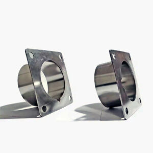
Larger plates distribute load over more of the slab surface and offer more flexibility in anchor hole placement—useful when reinforcement or edge conditions constrain individual hole positions. The trade-off is spatial: a surface-mount plate can consume roughly 6 inches or more of perimeter width, a design figure from commercial guidance that reflects the combined effect of plate size and placement. On narrow deck edges or stairs with restricted width, that footprint is a real constraint, not an aesthetic inconvenience.
Compact plates reduce that perimeter impact but demand tighter substrate control. With hole spacing reduced, the margin for repositioning an anchor to avoid rebar or meet edge distance requirements is smaller. A flat, consistent slab surface matters more for compact plates because any variation in bearing area—from a patched section, a joint, or surface relief—has a proportionally larger effect on how the plate sits. The level of substrate preparation that is acceptable for a larger plate may not be acceptable for a compact one.
The plate size decision should be made with perimeter dimensions, slab surface condition, and anchor layout constraints on the table—not resolved on the architectural drawings without input from the installation and structural side.
| Plate Approach | Space Consumption & Visibility | Anchoring & Load Considerations |
|---|---|---|
| Larger surface-mount plate | Approximately 6 in. or more around perimeter; high visual presence | Better load distribution; hole spacing offers flexibility, less constrained by precise slab conditions |
| Compact surface-mount plate | Reduced perimeter footprint; lower visual impact | Demands tighter substrate control; tighter hole spacing requires higher anchor precision |
Drainage and Waterproofing Beneath the Post
Waterproofing is the detail most likely to be left unresolved between trades on an exterior railing installation. The general scope of work assigns the waterproofing membrane to one contractor and the railing to another, and the interface between them—specifically, what happens at the point where a drill penetrates the membrane—often has no explicit detail.
When anchor holes are drilled through an existing membrane, the penetration creates a potential leak path. If the annular space around the anchor is not sealed, and if the membrane is not dressed and integrated around the penetration, moisture can migrate through the slab assembly. In exterior applications, this exposure can degrade both the anchor and the slab over time, with freeze-thaw conditions accelerating deterioration where water is allowed to accumulate. The failure does not typically present itself immediately—it develops gradually, which means it is often attributed to something other than the original installation detail.
The gap beneath the base plate is a separate concern. A plate that sits flush to the slab with no drainage provision can trap water, accelerating corrosion at the plate base and concentrating moisture at the anchor entry points. A shimmed or relieved plate that allows water to shed away from the post is the more durable configuration, but it requires a deliberate detail rather than a field decision.
Sealant selection and application method are not governed by ASTM E894, which addresses anchorage performance, not waterproofing. Sealing penetrations and managing drainage beneath the plate are commercial good practice decisions. The consequence of omitting them is not always visible during installation inspection, which is why the detail needs to be defined before drilling rather than addressed as a punch-list item afterward.
| Waterproofing Concern | Potential Issue | Что следует уточнить в подробностях |
|---|---|---|
| Anchor hole penetrations | Moisture can migrate through unsealed holes, degrading the slab or anchors | Sealant type, application method to fill annular space and cap |
| Water accumulation beneath base plate | Standing water may cause corrosion or freeze-thaw damage | Shim/gap design to allow drainage away from the plate |
| Waterproofing membrane continuity | Drilling may breach or tear the membrane, creating a leak path | How the membrane is dressed, sealed, and integrated around penetrations |
Coordinated Drilling Release Conditions
Issuing a drilling release is a coordination milestone, not a formality. By the time the first hole is marked, several conditions should already be confirmed—and if they are not, drilling should wait.
The conditions that warrant a release are: slab age sufficient to have reached design strength, anchor embedment capacity confirmed through the structural design, reinforcement and edge distance conflicts reviewed and resolved against the proposed layout, and a workable waterproofing detail in place for penetrations and plate drainage. Moisture content of the slab surface may also be relevant depending on the anchor adhesive system specified. None of these are testing pass/fail criteria in the sense that ASTM E894 describes for anchorage performance evaluation—they are design and coordination confirmations that belong earlier in the process.
The mistake pattern here is sequential rather than technical: layout proceeds because the railing contractor is on-site and the schedule is running, reinforcement clearances are assumed rather than checked, and the waterproofing trade has not yet provided a penetration detail. The result is a hole pattern that requires revision, a membrane that has been drilled without a remediation plan, and a coordination problem that is now more difficult to resolve because the concrete has already been disturbed.
A useful pre-drilling checklist framing: who has confirmed edge distances, who has reviewed the rebar data, who owns the penetration seal, and what is the plate drainage detail. If any of those questions cannot be answered by a named party before the drill is turned on, the release has been issued too early. For a closer look at anchor specification within this coordination sequence, the detailed guidance in Как крепить столбы из нержавеющей стали к бетонным поверхностям: Размеры анкерных болтов и требования к крутящему моменту is worth reviewing before finalizing anchor selection. Опорные плиты для поверхностного монтажа should be selected after those conditions are confirmed, so the plate geometry and anchor pattern are matched to actual slab constraints rather than assumed ones.
The most consistent source of rework in surface-mount railing installations is not fabrication error—it is premature drilling driven by incomplete coordination. Slab data, reinforcement review, edge distance confirmation, and a waterproofing penetration detail are not post-installation concerns; they are prerequisites to a reliable anchor layout. Treating them as such is what separates an installation that holds its geometry and durability long-term from one that requires anchor remediation or membrane repair within a few seasons.
Before layout is finalized, the questions worth resolving are concrete: what does the slab reinforcement look like at each post position, does the plate pattern fit within the available perimeter width given the plate size selected, who owns the penetration seal, and is there a drainage path beneath the plate. The answers to those questions determine whether the installation proceeds cleanly or accumulates problems that become visible only after the railing is loaded and the weather has done its work.
Часто задаваемые вопросы
Q: What if I can’t obtain rebar drawings or a GPR scan for my concrete slab?
A: If documentation and scanning are unavailable, perform a limited field verification by drilling small pilot holes at proposed anchor locations to check for rebar before committing the full layout. This adds schedule risk but is safer than drilling blind. For any slab that might be post-tensioned, treat tendon location data as mandatory—guessing can cause structural failure.
Q: After all pre-drilling checks are cleared, what is the actual sequence for marking and drilling the holes?
A: Start by transferring the approved layout to the slab with a template and center-punch marks. Drill a single test hole at a non-critical post first to confirm concrete consistency and true embedment depth, then verify the hole diameter and, if using chemical anchors, the adhesive cure time and moisture limits. Proceed with the full pattern only after that test hole passes.
Q: Is this level of coordination required for a small residential balcony with a thin, unreinforced concrete slab?
A: The review can be scaled down but not eliminated. For a slab known to be unreinforced and without post-tensioning, you can often skip the rebar scan and concentrate on confirming slab thickness, edge distances, and a waterproofing detail. Edge-distance requirements still apply—a post set too close to a slab edge will have reduced anchor capacity regardless of project size.
Q: When should I use epoxy-set anchors instead of mechanical expansion anchors for surface-mount posts on concrete?
A: Epoxy anchors are the better choice when high pull-out strength is needed, when anchors must be placed near a slab edge (they produce no expansion stress), or when the concrete quality is unknown—conditions common on exposed decks. Mechanical anchors work well in dry, known-quality concrete with generous edge clearances and offer immediate load capacity. The slab data gathered in the pre-drilling review will indicate which system fits the actual substrate.
Q: Is the expense of rebar scanning and coordinating with the waterproofing trade worth it for a single-family deck railing?
A: Yes—the cost of a few hours of scanning and an agreed penetration seal detail is typically far less than repairing a cut tendon or a leaking membrane a year later. Residential slabs have a lower risk of hitting rebar than commercial decks, but a single undiscovered conflict or water-ingress point can cause edge-of-slab damage and anchor corrosion that multiplies the repair cost. Pre-drilling coordination is relatively cheap insurance.