A base plate detail can look complete once the hole pattern, plate size, and weld symbol are drawn, and still leave a fabricator and an installer with conflicting assumptions about what is fixed and what is field-verified. The gap rarely shows up in the drawing review; it shows up at drilling, when the assumed slab edge or anchor spacing does not match what exists on site.
Рабочие чертежи, которые необходимо утвердить до изготовления опорной плиты
A base-plate detail carries several categories of information that belong together but are not equivalent in their reliability. Plate size and shape, the hole pattern, the post centerline, and the orientation of the plate edges relative to the structure it sits on are all drawing inputs. Where any one of these is fixed in isolation, without reference to the others, the detail can read as coordinated while actually leaving the fabricator to guess how the pieces relate once the plate lands on the actual slab, wall, or curb condition.
The distinction that matters before fabrication begins is between a dimension that describes the plate itself and a dimension that describes the plate’s relationship to the supporting structure. Plate thickness, hole diameter, and the spacing between anchor holes are properties of the fabricated part; they do not change once the plate leaves the shop. Post centerline location relative to a slab edge, a wall line, or an adjacent assembly is a site relationship, and it can shift for reasons that have nothing to do with the plate’s own geometry, including tolerances carried over from the structural frame or finish buildup that was not finalized when the drawing was issued.
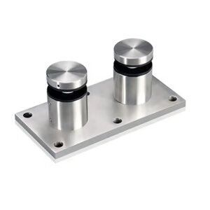
Where the base plate is a surface-mount type, resting on top of a finished or structural surface rather than embedded, the relationship between the plate footprint and whatever is beneath it becomes the primary coordination question, because the mounting surface, not the plate itself, sets the constraints on hole location and edge distance. Опорные плиты для поверхностного монтажа carry this dependency more directly than an embedded or core-drilled condition, since the plate’s final position is entirely a function of what exists on the surface it lands on.
Before fabrication proceeds, the drawing needs to show which values are being treated as fixed for shop purposes and which are being carried forward as pending site confirmation. A hole pattern drawn to a nominal centerline, with no note on what happens if the as-built centerline differs, forces a choice at the time of drilling that should have been made at the time of drawing release. That choice, made in the field without the original design intent in hand, is where inconsistency between units on the same project tends to originate.
Размеры опорной плиты и оси стоек на несущей конструкции
The core relationship a base-plate detail must express is how the plate’s own geometry maps onto the centerline of the post it carries, and how that centerline in turn maps onto the supporting structure below. These are three separate pieces of information, and treating them as one combined dimension is where drawings lose clarity. Plate size answers what the fabricated part is. Post centerline answers where the load path enters the plate. The structural relationship answers where that combination sits on the slab, curb, or framing member that will actually receive the anchors.
Edge orientation is the piece most easily left implicit. A rectangular or non-symmetric base plate has a defined relationship between its edges and the post centerline, and that relationship has to be fixed relative to the supporting structure’s own edge or reference line, not just relative to the plate’s own geometry. Where the plate is rotated or mirrored from what the shop drawing intended, the hole pattern can still land in a location that passes a simple dimension check while producing a post that leans away from or into an adjacent condition, because the edge-to-structure relationship was never separately dimensioned.
The consequence changes with the type of supporting structure. Where the post lands on a continuous slab edge with a straight, known reference line, the centerline dimension can be taken from that edge with reasonable confidence, because the reference itself does not vary along the run. Where the post lands near a curb, a stepped condition, a return, or an opening, the reference line is no longer continuous, and a centerline dimension that was valid for one post in the run may not transfer to the next one without re-establishing the reference locally.
This is also where the plate’s relationship to the structure needs to be shown on the same detail as the plate’s own dimensions, rather than split across a plan drawing and a separate plate schedule. A plate schedule that lists hole spacing without showing how that spacing maps to the structure leaves the fabricator with a correct part and the installer with an undimensioned relationship to resolve independently, and those two independently resolved interpretations are not guaranteed to agree with each other.
Расстояние между центрами отверстий, края плит, препятствия и доступ для сверления
| Координационный центр | Что должно быть изображено на рисунке | Решение, принятое до того, как схема расположения отверстий будет утверждена |
|---|---|---|
| Расстояние между центрами отверстий и кромкой плиты | Определите расстояние между центрами отверстий относительно края плиты. | Убедитесь, что предлагаемая схема расположения отверстий и взаиморасположение краев согласованы. |
| Бурение и доступ к инструменту | Укажите размеры, необходимые для доступа в местах расположения отверстий. | Убедитесь, что вопросы, связанные с планируемым бурением и доступом к инструменту, решены. |
| Прилегающие препятствия | Определите расположение бордюров, отделочных элементов, остекления и прилегающих стальных конструкций относительно схемы расположения отверстий и зоны доступа. | Выявите препятствие до того, как будет опубликована схема расположения отверстий. |
Once the plate and centerline relationship is fixed, the next layer of coordination concerns what surrounds the hole pattern physically, both on the surface the plate sits on and in the space needed to install it. Hole centers dimensioned only relative to the plate’s own edges say nothing about where those centers fall relative to the slab edge, and a hole placed too close to an edge changes the anchor’s effective capacity in ways that a plate-only dimension cannot reveal.
Access is a separate condition from location. A hole center can be correctly positioned relative to the slab edge and still be unusable if the tool needed to drill or set the anchor cannot physically reach that location, because a curb, a return wall, an adjacent glazing system, or nearby steel occupies the swing radius or approach angle the tool requires. This condition is easy to miss on a plan view, since plan views show clearances in one direction and installation access frequently depends on a vertical or angled approach that a flat plan does not represent.
Obstructions that were not present when the structural drawing was issued, or that belong to a different trade’s scope, are the recurring source of conflict here. Finish buildup, a curb added after the structural slab was poured, or steel from an adjacent system can all occupy space that the base-plate detail assumed was open. Where the hole pattern is finalized before these adjacent conditions are confirmed, the drawing is describing an installation that may not be achievable exactly as drawn, and the conflict surfaces only when the crew is on site with tools in hand.
The order of confirmation matters: hole-to-edge relationship, then access for the specific drilling and anchor-setting method intended, then a check against whatever adjacent obstruction inventory exists for that location. Skipping the access check because the hole-to-edge dimension looks satisfactory is how a plate that fits its own dimension set still fails to install as drawn.
Допуски, относящиеся к процессу изготовления, и допуски, относящиеся к проверенным условиям на объекте
| Проведение разграничения | Что указать | Граница принятия решения |
|---|---|---|
| Допуски на изготовление | Определите, какой размер затронут, и укажите его технологический допуск. | Указывает допуск, установленный при изготовлении; данное значение не заменяет проверенных измерений на объекте, если таковые требуются. |
| Проверенное состояние объекта | Определите соответствующий размер и соотнесите его с проверенными данными измерений на объекте. | Предотвращает трактование значения, зависящего от конкретного объекта, как фиксированного номинального размера; не устанавливает допуск на изготовление. |
| Комбинированная центровка | На чертеже детали следует отдельно указывать производственные допуски и размеры, зависящие от конкретных условий монтажа. | Выявляет накопленные несоосности для обеспечения координации, а не скрывает их в единой номинальной схеме расположения. |
A single nominal dimension on a base-plate detail can represent two very different kinds of information, and the drawing needs to distinguish between them explicitly rather than let the reader assume. Some dimensions describe what the fabricator controls directly: plate thickness, hole diameter, the spacing between holes on the plate itself. These carry a fabrication tolerance, a range within which the shop process is expected to hold the dimension, and that tolerance is a property of the manufacturing method, not of the project site.
Other dimensions describe a relationship to something the fabricator does not control: the actual location of a structural edge, the actual elevation of a finished surface, the actual position of an embedded anchor that was set before the plate was designed. These depend on a verified site measurement, and no fabrication tolerance can substitute for that verification, because the fabrication process has no influence over where the existing structure actually sits.
The risk appears when both kinds of dimension are shown as a single nominal value with one tolerance band applied uniformly, because that treatment implies the site condition is as controllable as the shop process, when it is not. A hole pattern that is nominally correct relative to a drawn slab edge, combined with a fabrication tolerance on hole spacing, can still be wrong at the point of drilling if the real slab edge was never verified against the nominal value used in the drawing. The error does not originate in the plate; it originates in treating an unverified assumption as though it were a controlled dimension.
Where multiple such dimensions compound, for instance a centerline taken from an assumed slab edge, combined with a hole spacing taken from an assumed post size, combined with a cover dimension taken from an assumed fastener projection, each individual tolerance may be small while the combined misalignment at the last interface is not, because tolerances stack rather than cancel unless the drawing tracks them separately. Keeping fabrication tolerance and site-verified dimension visually and numerically distinct on the detail is what allows that cumulative effect to be checked before it becomes a field problem, rather than being discovered only when the last piece does not sit where it was expected to.
Крышки, сварные швы, дренаж и конфликты с головками крепежных элементов на одном чертеже
| Вопрос о координации | Элементы для совместного отображения | Граница выпуска |
|---|---|---|
| Установится ли крышка без конфликта интерфейсов? | Крышка, сварные швы и открытые головки крепежных элементов | Само по себе соответствие отверстий для анкерных болтов ещё не означает, что крышка расположена в соответствии с местами сварных швов и головками крепежных элементов. |
| Не перекрывают ли окружающие интерфейсы путь дренажа? | Дренажный канал, крышка, сварные швы и открытые головки крепежных элементов | Само по себе соответствие анкерного отверстия ещё не означает, что путь отвода воды не создаёт конфликтов. |
| Все интерфейсы были рассмотрены в комплексе? | Отверстия для анкеров, крышка, сварные швы, канал отвода воды и выступающие головки крепежных элементов | Не выводить деталь только для посадки в анкерное отверстие; согласовать остальные сопряжения на той же детали. |
A base plate detail that resolves the anchor hole pattern completely can still fail at release if the items that sit on or around that same footprint were never checked against each other. Cover plates, welds, drainage provisions, and exposed fastener heads all occupy the same physical zone as the anchor holes, and each has its own geometry that can conflict with the others even when none of them conflicts with the anchor pattern itself.
A cover plate designed to conceal the anchor heads has its own footprint and fastening method, and that footprint needs to clear the weld that attaches the post to the base plate, since a weld bead that intrudes into the cover’s seating area will prevent the cover from sitting flush regardless of whether the anchor holes underneath are correctly placed. Similarly, an exposed fastener head that was sized for one anchor type may project further than a cover plate’s clearance was designed to accommodate, producing a fit conflict that has nothing to do with hole location.
Drainage is the condition most likely to be treated as separate from the structural hardware when it is not. Where a base plate sits in a location exposed to water, whether from weather or from a washdown condition, a drainage path needs to be maintained clear of the plate, the cover, and the fastener heads together, not just clear of the plate footprint alone. A drainage slot positioned correctly relative to the plate but blocked by a cover plate’s edge, or by a weld fillet that was not accounted for, defeats the drainage provision without any single component being out of its own tolerance.
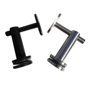
The reason these conflicts survive into installation is that each item is frequently drawn or specified by a different party: the anchor layout from the structural engineer, the cover detail from the hardware supplier, the weld from the fabricator’s shop drawing, and the drainage intent from the architect’s performance requirement. None of these parties individually sees a conflict, because each is checking their own item against the anchor pattern rather than against the other add-on items. The detail that shows all of them together, at the same location, in the same view, is the only place that conflict becomes visible before fabrication, which is also where product selections drawn from a source such as Post Hardware & Mounting need to be checked against the specific cover and fastener combination intended for that plate rather than assumed compatible by family.
Проверка согласованности размеров, интерфейсов и сфер ответственности при выпуске
Releasing a base-plate detail for fabrication means confirming that the three coordination layers already described are resolved together, not independently. The hole pattern has to be checked against the slab edge and against drilling access before it is frozen. The tolerance treatment has to distinguish fabrication-controlled dimensions from site-verified ones, so that cumulative misalignment is visible rather than buried in a single nominal number. The add-on items around the plate, cover, weld, drainage, and fastener heads, have to be checked against each other on the same detail, because anchor-hole fit alone does not confirm that those interfaces are free of conflict.
Where a project’s structural documentation follows a format similar to a metal-railing specification structure such as UFGS 05 52 00, the submittal process itself is built around exactly this kind of layered check, requiring shop drawings that show dimensions, connections, and anchorage together for review before fabrication proceeds; that structure is an example of how a submittal package can be organized and is not a requirement that applies independent of what a specific project actually specifies. Separately, where the applicable design and performance expectations for a permanent metal railing system are drawn from a source such as ASTM E985, the base-plate detail sits downstream of whatever criteria the project has adopted from that standard, and the standard’s own text, not the general description of its scope, is what the project team needs to confirm the detail against.
The condition that determines which check matters most on a given project is how many of the three layers were already resolved earlier in design versus how many remain open at the point of release. Where the post centerline and structural relationship were fixed early and verified against as-built conditions, the remaining release check is largely the interface layer, covers, welds, drainage, fasteners, since the dimensional foundation is already settled. Where the structural relationship itself is still carrying assumed rather than verified values at the point of release, the interface check cannot resolve the underlying risk, because a coordinated cover and drainage detail built on an unverified centerline is still built on an unverified centerline.
Responsibility for closing each of these checks belongs to whichever party controls the information the check depends on: the site-verification items belong with whoever surveys or confirms as-built conditions, the fabrication-tolerance items belong with the fabricator producing the plate, and the interface coordination among cover, weld, drainage, and fastener belongs with whoever is assembling the full detail from each contributor’s input. A base-plate detail that has been checked against all three layers, with each party’s contribution distinguishable on the drawing, is what allows the detail to be released without leaving an unresolved assumption for the installation crew to interpret on site. For the information a buyer provides into a configuration or quotation review, the plate size, hole centers, post centerline, and edge orientation described on such a detail are the specific inputs that determine which base-plate configuration can be quoted and supplied for that location.
Часто задаваемые вопросы
Вопрос: Какую информацию необходимо уточнить до того, как будет утверждён схема расположения отверстий в опорной плите?
A: Уточните размеры плиты, расстояние между центрами отверстий, осевую линию стойки, расположение по отношению к краю плиты и ориентацию края на одном согласованном чертеже. Кроме того, перед утверждением шаблона определите расположение бордюров, отделочных материалов, остекления, прилегающих стальных конструкций, а также пространство, необходимое для сверления и доступа к инструменту.
Вопрос: Как на чертеже следует различать допуски на изготовление и размеры, зависящие от условий монтажа?
A: Обозначьте затронутые размеры отдельно и укажите, какие допуски применяются при изготовлении, а какие значения требуют подтверждения измерениями на месте. Проанализируйте их совокупное влияние на выравнивание, а не объединяйте их в одну номинальную разметку.
Вопрос: Считается ли, что опорная плита установлена правильно, если анкерные отверстия совпадают?
A: Нет. Эту же деталь следует также проверить на наличие конфликтов между крышкой, сварными швами, дренажным каналом и выступающими головками крепежных элементов, поскольку любой из этих сопряжений может остаться нерешенным, даже если отверстия совпадают.
Вопрос: Является ли ссылка на технические условия или стандарт, касающиеся перил, доказательством того, что чертеж опорной плиты соответствует им?
A: Нет. Ссылки, такие как UFGS 05 52 00 или ASTM E985, могут помочь в организации процесса экспертизы проекта, однако применимые критерии должны быть подтверждены в контексте конкретного проекта и соотнесены с полным текстом соответствующего документа; одной лишь ссылки недостаточно для подтверждения соответствия продукта или чертежа.