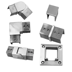
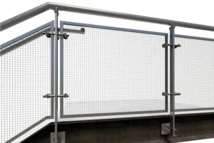
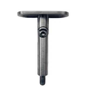
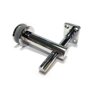
A continuous handrails and joints specification starts with the rail path, not the hardware: define the full usable gripping run through straight sections, turns, stairs, landings and terminations, then select the joints that let a fabricator build that run and an installer fit it. Continuity here means an uninterrupted graspable surface along the defined path, which is an assembly and geometry problem rather than an appearance one. Two site conditions change the answer more than anything else: where the rail is supported, and how long a piece can be transported and carried into position.
Define the continuous usable rail path
Draw the usable rail path first, as a single line that follows the walking surface from the start of the run to its end, including stair flights, intermediate landings, turns and the way the rail stops at each end. Until that line exists on a drawing, a joint schedule has nothing to coordinate against, because a splice position only means something relative to a support, a turn or a termination.
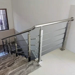
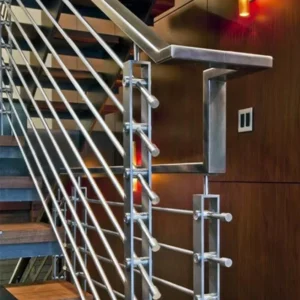
Walk the line in the order you would install it. A straight wall-mounted run on a corridor may need nothing more than brackets at regular centers, but the moment the path turns a corner, climbs a flight, crosses a landing and resumes, you are dealing with changes of plane as well as changes of direction. Each of those changes is either a bend formed in the tube, a fitting, or a joint, and each choice affects whether the grip stays continuous through the transition.
Terminations deserve the same attention as the middle of the run. The way the rail ends determines whether the last piece can be a straight length with an end cap, a returned bend back to the wall or post, or an extension carried past the top or bottom riser. Those decisions set the length of the end segments and therefore where the nearest joint can sit.
Accessibility requirements are the part of this that you cannot decide from geometry alone. The Access Board’s guide to stairways covers handrail continuity, gripping surfaces, clearance and extensions on covered means-of-egress stairs in U.S. accessible facilities, and it is the kind of requirement that sets the rail path before any product selection. Whether your project is covered, and which adopted requirements apply, depends on jurisdiction and the use of the building, so confirm coverage with the responsible designer and record the result on the same drawing that carries the path.
Coordinate joints with supports and access
Put splice positions, support positions, the behavior of each connection and the installation access onto one layout, and review them together. A splice chosen only to suit a convenient shipping length can land mid-span between brackets or posts, or in a position where no one can reach the fasteners once the adjacent components are in place.
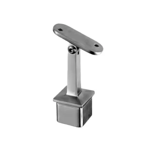
The relationship to supports is the first thing to check. A joint near a bracket or post sits in a region where the rail is held by the structure; a joint at mid-span relies entirely on the connection itself to carry the rail’s continuity across that point. Which positions are acceptable, and what each joint has to do structurally, comes from the responsible project designer, because that depends on the guard and handrail loads the system is designed for and on the support spacing chosen for them. What you can do at the specification stage is make the question explicit: mark every splice on the layout, mark every support, and state what function each splice is required to perform.
Access is the second check and it is purely physical. A sleeve or connector that needs a set screw tightened from below is unusable where the rail sits tight to a soffit; a connector that needs end access for assembly cannot be installed between two already-fixed segments. Follow the assembly sequence in your head, piece by piece, and ask at each joint which direction the fitter approaches from, what tool fits in that space, and whether the adjoining component is already fixed at that point.
The third check is what happens later. Damage to a handrail in a public stair or corridor is normal service life, so decide now whether a damaged segment can be removed without cutting the rail or disturbing the finish on neighboring pieces. If replacement matters to the owner, that argues for mechanical joints at positions reachable after completion, and it argues for recording those positions in the project record rather than leaving them to the fabricator’s shop drawings alone.
Choose shop and field connection routes
| Connection route | Planning consequence | Condition to resolve before selection |
|---|---|---|
| Shop welding | The shop-finished connection changes transport constraints. | Confirm how the connected assembly fits the project’s transport modules. |
| Mechanical field joints | The field connection changes site assembly and inspection tasks. | Confirm assembly access and the field-assembly and inspection responsibilities. |
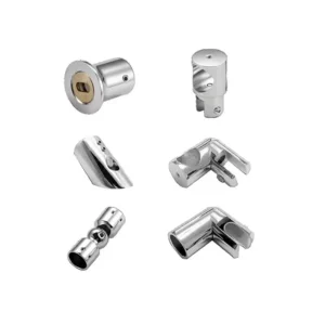
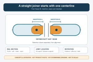
The choice between shop welding and mechanical field joints is a choice about where the work happens and what it constrains, so compare finish work, assembly access, replacement needs and the documented function of each joint before you name a method. A shop weld, ground and finished to match the rail, gives a joint with no visible line and nothing to loosen, but it fixes the assembly’s size and shape from the moment it leaves the shop. A mechanical joint, whether a sleeve, internal connector or threaded fitting, keeps pieces separable, but moves finishing, alignment and verification onto the site.
The transport question is concrete and easy to resolve early. Work out the longest assembly that can be loaded, shipped, carried through the building’s access route, and maneuvered around any stair turn or landing. That length is the transport module, and it determines the minimum number of connections regardless of which route you prefer. A continuous rail up a stair core with tight half-landings often cannot receive a long welded assembly even when the truck could carry it.
The site-assembly question is equally concrete, in the other direction. A field connection adds alignment, tightening and finishing tasks at height, often on temporary access, and it adds a junction that someone will look at during inspection. Decide who performs that work and who checks it, because an undefined field-assembly responsibility is where coordinated specifications usually come apart.
A reasonable starting position for a long straight exterior run with clear access is shop-welded assemblies broken only where transport forces it, with the breaks placed near supports. A reasonable starting position for a stair core with tight turns and a likely need for future replacement is mechanical joints at planned positions. Where the project names a joint system or a fabrication method, that instruction governs and the comparison narrows to how the named method is detailed. If your project is a stair, the indoor, outdoor and continuous-rail selection questions for stair handrails are worth settling before the joint method, since exposure and mounting condition also bear on the fabrication choice.
Check profile compatibility and movement interfaces
Confirm mating dimensions, orientation and intended fit across the actual set of tubes, connectors, sleeves and bends you intend to buy, not against nominal profile names. Tube dimensional standards such as ISO 1127, which covers stainless steel tube diameters, tolerances, other tube parameters and conventional masses, let you identify and order consistent stock, and that dimensional scope is exactly where their usefulness ends: they say nothing about railing load capacity, surface finish, weld quality or code compliance, and they do not tell you how a particular connector seats inside a particular tube.
That gap matters most with internal connectors and sleeves, where the fit depends on the inside dimension of the tube after its wall thickness and manufacturing tolerance, and on the finish inside the tube end. Two tubes with the same nominal outside diameter can have different bores and accept the same sleeve differently. The practical check is to confirm, for the specific components, the outside diameter and wall thickness of the tube, the bore or spigot dimension of the connector, and how much adjustment the fit allows at assembly. Where a manufacturer offers a documented assembly of tube, bends and connectors designed together, that check is simplified because the matching has already been coordinated; where you are mixing sources, do the comparison component by component.
Orientation is the second half of compatibility. Elbows, segment bends and wall returns are made for particular angles and planes, and a fitting that is dimensionally correct can still be wrong for a stair-to-landing transition if it only turns in one plane. State the required angles on the layout and confirm that the component set can produce them.
A long exposed run or a rail that crosses a building movement interface, such as an expansion joint or a structural break between frames, raises a different question. A rail that looks rigid and continuous is still fixed to a structure that moves, and thermal expansion over a long exterior run plus relative movement at a building joint will go somewhere. Identify the movement the project requires the rail to accommodate, get that figure from the responsible project designer, and coordinate any slip joint, sliding sleeve or discontinuity in the support detail with the joint schedule, because the accommodation only works if the adjacent supports allow the rail to move. Both the required movement and the joint arrangement that handles it have to be set for the actual project rather than assumed from the rail profile.
Issue the joint, support and installation schedule
Release the package with a joint and support schedule that locates every splice and every bracket or post on the defined rail path, states what each joint is required to do, and gives the profile and finish references for the rail and the connecting hardware. This is what turns a desired continuous rail into something a fabricator can shop-draw, a carrier can deliver and an inspector can check, instead of leaving each fabricator to pick splice positions independently and discover the clashes on site.
Alongside the schedule, state the transport modules you have accepted, so the fabricator knows which breaks are fixed by access and which are open to its own shop planning. Assign the field-assembly responsibilities explicitly: who sets the supports, who makes each field connection, who aligns and finishes it, and who performs any site welding and its finishing. Then state the inspection requirements for those junctions, including what evidence is expected and at what stage.
Two things stay open rather than being resolved by the schedule. Any unresolved movement requirement or connection design belongs with the responsible project designer and should be flagged as outstanding rather than filled with an assumption, and any acceptance of the installed assembly is decided through the project’s approved procedure by its designated approver, not by the fabricator’s own confirmation that the pieces fit. Mark both clearly in the issued documents so no one treats them as settled.
For a productive conversation with a handrail supplier about continuous handrails and joints specification, have the rail path layout with supports and intended splice positions marked, the profile, tube wall thickness and finish, the stainless grade suited to the exposure, the transport and site access constraints, the required accommodation for movement if any, and the inspection and submittal expectations. With those in hand, the supplier can respond on connector families, bend capability and assembly fit rather than guessing at the geometry. The same material converts directly into the drawings, material certificates, load documentation and finish samples that the project submittal package will ask for.
Frequently Asked Questions
Q: Does a continuous handrail have to be made as one welded piece?
A: No. Continuity concerns the usable rail path through the complete assembly; a seamless appearance alone does not establish it. A jointed arrangement still needs a defined connection function and coordinated transitions, supports and ends. Check the project’s applicable accessibility requirements separately.
Q: Can we choose splice positions just by dividing the rail into convenient shipping lengths?
A: Use shipping lengths as a transport constraint, not the sole basis for splice positions. Put the proposed breaks, supports and installation access on the same layout before fixing the modules. Resolve any unsupported or inaccessible junction, with structural details provided by the responsible project designer.
Q: Is matching the nominal tube size enough when buying connectors separately?
A: No. Confirm the actual mating profile dimensions, orientation and intended fit across the selected rail, connectors, sleeves and bends. A nominal profile name does not settle the completed connection or its assembly tolerances. A documented matched assembly can simplify this check.
Q: Can a rail crossing a building movement interface use the same joint detail as the rest of the run?
A: Do not assume that it can. Establish the relative movement the project requires the assembly to accommodate, then coordinate the joint and supports for that location. Keep the connection design open before release if the required movement or accommodation remains unresolved.