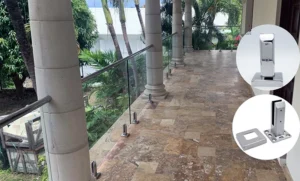
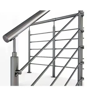
A railing post retrofit starts with a survey of what is already there, because the existing anchorage determines whether the replacement post can land on the same footprint or needs a new base and local support work. Before anything is ordered, you establish how each post currently connects to the supporting construction — embedded in the slab, surface mounted on a base plate, side mounted to a fascia or edge, or welded to steel — and you record that classification by location along with the physical condition of the holes, plates, welds, concrete and finishes around it. Existing anchors and holes stay candidates for project-specific evaluation; whether any of them carry the replacement post is decided by the responsible project designer against the proposed configuration and the applicable loads, not by the fact that they held the old post.
Identify the Existing Post and Anchorage Route
The first survey pass sorts every post into one of four connection types and names what it connects to. Embedded posts pass through the slab or stair tread and are grouted or cast in. Surface-mounted posts sit on a base plate on top of the walking surface with anchors into the substrate below. Side-mounted or fascia-mounted posts bolt to a vertical face — a slab edge, a stringer, a curb — so the load arrives as a prying couple on the face rather than compression on a flat plate. Welded posts are fixed directly to a steel frame, embed plate or stringer with no mechanical fastener to remove.
The distinction matters because it decides where the load goes and what you can physically change. A surface-mounted base keeps the structural demand in the top of the slab, close to the finish, and the anchors sit in a shallow zone. A fascia mount moves demand into the slab edge, which is the part with the least material around it. An embedded post puts the moment deeper into the section but leaves you with a grouted pocket to break out rather than bolts to undo. A welded connection changes the removal method entirely and brings the condition of the parent steel into the retrofit scope.
Record the classification per post, not per run. Mixed conditions along a single run are normal in older work — surface-mounted posts on the flat, fascia mounts at a slab edge, an embedded post at a stair nosing — and a run that looks uniform from standing height often is not once you get down to the base. Note what the post connects to as well: cast-in-place slab, topping over precast, steel stringer, masonry curb. That construction type governs what repair or new anchorage is even possible later.
Survey Holes, Base Plates, Embedments, Welds, and Repairs
| Item da pesquisa | Record by location | How it informs the retrofit |
|---|---|---|
| Existing holes | Hole location and visible condition | Keeps each hole as a candidate for project-specific evaluation rather than assuming it can be reused |
| Base plates | Plate location, post connection, and visible condition | Identifies a surface-mounted condition for comparison with the proposed post configuration |
| Embedments | Embedment location and visible connection to the supporting construction | Identifies an embedded condition that the replacement detail must address |
| Welds | Weld location and the connected post and supporting construction | Identifies a welded condition that the replacement detail must address |
| Existing repairs | Repair location and adjacent finish condition | Flags where local support work or finish repair may need separate coordination |
This section of the survey captures the physical evidence at each anchorage point and ties every observation to a location on the drawing or a tagged post number. Document existing holes, base plates, embedments, welds, previous repairs, visible corrosion, cracks, edge geometry, finishes and removal access, each referenced to where you found it. A location-keyed record is what lets a designer evaluate post 14 on its own evidence instead of applying a run-wide assumption.
Existing holes deserve particular care, and they are worth photographing and measuring individually. A hole tells you the bolt pattern and the edge distance the original installer worked to, and whether the surrounding concrete is sound or has already spalled around the anchor. It does not tell you the residual capacity of that hole, which depends on the substrate condition, the anchor type that would go back in, and the loads the replacement guard must carry. Treat each hole as an item for evaluation and give the designer the dimensions, the spacing, the distance to the free edge and the condition of the material around it.
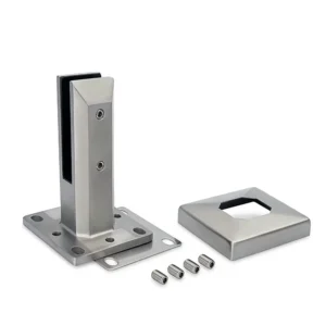
Base plates carry their own evidence. Note the plate outline and thickness where you can measure it, the number and position of fastener holes, whether the post-to-plate connection is welded or mechanical, and whether the plate sits level or has been shimmed. Shim stacks, elongated holes and added washers usually mean the original setting-out did not match the structure, and the same mismatch will meet the new posts.
Embedments and welds are recorded by what they join. For an embedded post, note the pocket size if visible, the grout condition and any staining at the interface, which can mean water has been reaching steel inside the pocket. For a welded post, note the weld location, its visible condition and the member it lands on; the Federal Transit Administration’s rail tunnel inspection research, FTA Report No. 0236, describes checking connection welds and loose or missing bolts and documenting defect severity and location as part of inspecting rails, posts and railing anchorages — a useful model for the level of detail worth capturing, though that document is bounded to rail tunnel and ancillary stair inspection rather than general building retrofit.
Earlier repairs are evidence in their own right. Patched concrete, an added plate, a welded-on collar or a resin injection around a bolt all mark a location that has already moved or failed once. Those locations are where local support work and finish repair are most likely to appear as separate scope, so flag them while you are on site and can still see what was done.
Record Cracks, Corrosion, Edge Geometry, and Hidden Access
Condition and geometry around the anchorage decide whether the existing location can take a fixing at all, so record them with the same location discipline as the hardware itself. Note cracking, delamination, spalling, exposed reinforcement, moisture and corrosion staining in the concrete around each post. The FTA inspection research lists the same family of defects for concrete stairs alongside railing anchorage checks, which is a reasonable indication of the condition set worth capturing even though that guidance was written for rail tunnel and ancillary structures.
Corrosion is read in two places. On the railing itself, look for section loss, broken or missing members and staining running down from the base — rust bleeding out of a base plate interface usually means water has been standing under the plate and working on the anchors you cannot see. On the substrate, corrosion staining on concrete often signals reinforcement or an embedded plate corroding below the surface, which changes the repair scope well beyond the post. For coastal or chloride-exposed sites, record the exposure condition in the survey, because it affects both the condition you are seeing now and the stainless grade and finish specified for the replacement.
Edge geometry is the measurement most often skipped and most often decisive. Measure the distance from each existing hole or plate edge to the free edge of the slab, the nosing, the drip edge or the expansion joint, and record the slab or curb thickness where you can establish it. Edge distance governs what anchor can be used and how much concrete is available to resist a prying load, and a base plate with a larger footprint than the original cannot always be centered on the old location without pushing fasteners closer to the edge. If the replacement uses a different mounting family — a surface-mounted base plate where a core-mounted post was, for example — the new fastener pattern has to fit the geometry you measured, not the geometry you assumed.
Access is the last item and it drives program as much as it drives method. Record what sits below, behind and around each post: a soffit, a waterproofing membrane, a finished ceiling, a tiled terrace, an occupied space. Note whether the post can be removed from above, whether a core or a grouted pocket can be broken out without disturbing the membrane, and whether the finish around the base can be reinstated or will need replacement. Hidden access is the condition that turns a straightforward post change into a sequenced trade operation, and it is cheaper to discover it during the survey than during demolition.
Compare Measured Conditions With the Replacement Configuration
| Ponto de comparação | Existing-condition evidence | Proposed-condition input | Decision to document |
|---|---|---|---|
| Anchorage interface | Anchorage route, existing holes or anchors, and connection to the supporting construction | Proposed post mounting configuration | Whether the existing interface remains a reuse candidate for project-specific evaluation or a new base or local support solution needs review |
| Run geometry | Measured run geometry | Proposed post configuration along the run | Locations where the two do not align and new bases or local support work may need separate coordination |
| Transition points | Measured transition locations and existing interface conditions | Proposed post configuration at each transition | Locations where the transition requires separate coordination for the base, supporting construction, or finish repair |
The comparison step sets the surveyed interface against the proposed post layout and finds every location where the two do not agree. You are matching three things: the anchorage interface at each post, the measured run geometry over the whole length, and the condition at each transition — corners, level changes, stair-to-landing junctions, expansion joints and terminations. Each mismatch becomes a documented decision rather than a field adjustment.
Run geometry is where disagreements surface in volume. Existing posts were set to a spacing that suited the original design and the original structure, and a replacement configuration with different spacing will put some bases on sound material and others over a joint, a patch or a hollow. Overlay the proposed post positions on the measured positions and mark the offsets. Where the offset is small, you are asking whether the new base can still clear the old hole and keep acceptable edge distance; where it is large, you are asking whether a new base, local support work or a different mounting family is required at that location.
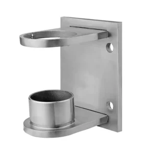
Transitions deserve separate treatment because they concentrate several conditions at once: reduced edge distance, a change in substrate, a finish junction and often a previous repair. The decision to document at each transition is whether the base, the supporting construction or the finish needs coordination with another trade, and what that coordination has to achieve. A surface-mount base plate, a fascia-mount plate and a core-mount system each make different demands on the material at that point, and choosing between them at a transition is a structural question before it is a hardware question.
Keep the comparison in terms of evidence and proposed input, not conclusions. The measured condition is what you found; the proposed configuration is what the drawing asks for; the output is a list of locations with a named issue. That list is what a designer can act on.
Route Reuse Decisions to the Responsible Project Designer
Whether an existing anchor or hole can be reused in the replacement detail is a project-specific evaluation and belongs to the responsible project designer, working to the project’s approved procedure. The survey supplies the evidence — hole positions, edge distances, substrate condition, corrosion, prior repairs, connection type — and the designer decides what, if anything, carries load again. No condition observed in the field substitutes for that decision, and an anchor that visibly held the previous post is not thereby qualified for the new one.
This division follows the way guard standards are written. ASTM E985-24, covering permanent metal railing systems and rails for buildings, sets out basic design, load and deflection criteria in its scope, while leaving specific field-condition design to the designer, specification writer and code agencies; the standard’s scope also excludes ballasted systems and certain adult-only workplaces governed by occupational-safety rules. It establishes neither anchor or hole reuse nor residual capacity at an existing location, which is precisely why those questions travel to the project’s designer with the survey attached.
What you can do is make that evaluation easy to complete. Present each candidate reuse location as its own item: the post reference, the connection type, the hole or anchor in question, the measured edge distance and spacing, the substrate condition, and any repair history. Flag locations where reuse is clearly not on the table — cracked or spalled concrete at the fixing, exposed reinforcement, corrosion staining through the slab edge — so the review effort goes to the locations where the answer is open. Where a location has no viable reuse path, the question shifts to which new base and what local support work are needed, and that is a design question too.
Release the Retrofit Detail With Traceable Survey Evidence
| Release evidence | Location-specific record | Decisão apoiada |
|---|---|---|
| Existing anchorage route | Post location, route classification, and connection to the supporting construction | Basis for the replacement mounting configuration |
| Anchorage and substrate condition | Holes, base plates, embedments, welds, repairs, visible corrosion, cracks, and edge geometry | Basis for any project-specific reuse evaluation or local support work |
| Geometry comparison | Measured run geometry and transition points compared with the proposed post configuration | Basis for locations requiring new bases or separate coordination |
| Access and finish condition | Removal access and existing finishes by location | Basis for removal planning and finish repair coordination |
| Reuse decision | The specific existing anchor or hole and the responsible project designer’s evaluation | Confirms that reuse is a project-specific decision rather than an assumption |
The retrofit detail is released when every replacement decision can be traced back to a recorded condition at a named location. Each post in the issued detail should connect to its survey entry: the original connection type and what it joined, the anchorage and substrate condition found there, the geometry comparison against the proposed layout, the access and finish situation, and the designer’s evaluation of any anchor or hole proposed for reuse. Where a location carries a decision that is still open, it is marked open rather than drawn as resolved.
Traceability does practical work on site. When an installer opens up a base and finds something the drawing did not show, the survey record is what shows whether the condition was known, missed or changed since. When a finish repair or local support item is disputed later, the location-keyed record shows when it was identified and on what evidence. Photographs tagged to post references are worth more than a summary paragraph, because they survive the project and can be re-read by someone who was never on site.
For a productive conversation with a railing supplier at this point, have the survey record ready in a form that can be read per location: the post classification and connection, the measured hole patterns, edge distances and slab or fascia dimensions, the proposed post spacing and mounting configuration, the exposure condition and the specified stainless grade and finish, and the access constraints at each base. With those in hand, ESANG can work from the actual interface at each post — surface-mount, fascia-mount or core-mount base systems, and any hardware made to the project drawings — rather than from an assumed footprint. What remains outside that discussion is the structural verdict on reuse and on any local support work, which stays with the project designer and the approver named in the project’s procedure.
Perguntas frequentes
P: Can an RFQ begin before every existing anchor or hole has been approved for reuse?
A: Yes, if the RFQ clearly separates confirmed survey facts from unresolved reuse decisions. Identify each location, existing anchorage route, measured geometry, access and finish conditions, and proposed post configuration, then mark any anchor or hole that still requires project-specific evaluation.
P: Can several similar-looking railing posts share one retrofit detail?
A: Only after their location records show that the anchorage route, supporting interface, run geometry, transition conditions, visible condition, and removal access are sufficiently alike. Keep any location with a different connection, repair, crack, corrosion condition, or geometry mismatch as a separate coordination item.
P: What should be checked before changing from an embedded or welded post to a surface-, fascia-, or core-mounted replacement?
A: Treat the change as a new interface decision for the supporting construction. Compare the measured edge and run geometry, available removal and installation access, existing connection, proposed mounting configuration, and likely finish-repair area before selecting the replacement route.
P: What if the existing connection cannot be confirmed during the first survey?
A: Record the location as unresolved rather than inferring the concealed condition. Note what prevents confirmation, such as limited access or an existing finish or repair, and define the additional access or project-specific review needed before the retrofit detail is released.
P: Does an earlier repair around a railing post prove that the location is suitable for reuse?
A: No. Treat the repair as condition evidence, not approval of the underlying anchorage. Record its location, the adjacent finish and any visible cracking or corrosion, then have the responsible project designer determine whether the interface remains a reuse candidate or needs separate local support and finish-repair coordination.