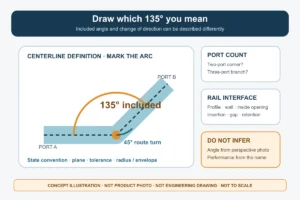
Start by measuring the installed rail against the approved shop drawings, not by looking for a part to blame. Misaligned post-mounted handrails usually show up as a visible kink, a swing in rail height, or a joint that will not close, and the same symptom can come from four different places: where the post sits, how the saddle or bracket faces, the rail profile itself, or a connector joint that is not seated. Which one it is changes what you can correct in the field and what has to go back to the project designer — and movement at the post base is a separate question from fit between rail and post.
Observed Pattern and Reference Geometry
| Observation to record | Reference or comparison | Diagnostic value and limit |
|---|---|---|
| Installed rail centerline | Approved shop drawings | Shows where the rail path differs from the approved geometry; the difference alone does not identify the responsible interface. |
| Installed rail elevations | Approved shop drawings | Shows where elevation differs from the approved geometry; the comparison should precede bracket changes or component cutting. |
| Location and direction of deviations across level, stair, or ramp runs | Recorded pattern across the run | A repeated direction can focus the investigation on an affected interface, but it does not prove root cause. |
Before any bracket is loosened or any tube is cut, compare the installed rail centerline and elevations with the approved shop drawings. That comparison establishes the reference geometry the run was supposed to follow, and it is the only way to say whether the rail has drifted off the approved line or whether the drawing itself places the rail where it now sits.
The reason to do this first is practical. If you adjust brackets to make a run look straight by eye, and the approved geometry put the rail somewhere else, you have added a second deviation on top of the first and removed the evidence of the original one. Measure, then record, then decide.
Record the location and direction of each deviation along the run, and keep level, stair and ramp sections identified separately. A repeated direction — for example, every rail sitting consistently toward the outside of the guard line, or elevations creeping low as the run progresses — tells the project team which interface to examine first. It narrows the investigation; it does not prove the cause, because post setting-out, bracket orientation and tube straightness can each produce a drift that accumulates in the same direction.
It helps to note what you measured against as well as what you measured. A centerline offset taken from a finished floor that is itself out of level reads differently from one taken from a structural datum. Where the shop drawings name the datum, use it; where they do not, state in your record which reference you used so later readings can be compared with yours.
Post Position Versus Bracket Orientation
| Check area | What to compare or isolate | Decision value |
|---|---|---|
| Post position | Installed post position against the approved geometry | Indicates whether the visible offset begins at the post location. |
| Saddle or bracket orientation | Orientation at the affected location, considered separately from post position | Indicates whether the offset begins at the saddle or bracket rather than at the post location. |
| Post-to-substrate movement | Movement at the post-to-substrate interface, separated from rail-to-post fit | Prevents an anchorage or structural concern from being mistaken for a component mismatch. |
Separate three things at every suspect location: where the post is, how the saddle or bracket is oriented, and whether the post moves at its base. These are distinct interfaces, and each one produces an offset that looks similar from a few meters away.
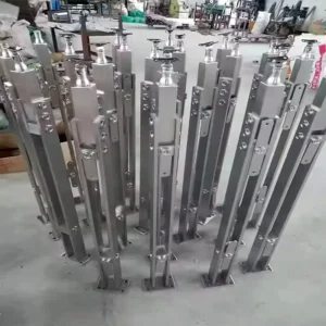
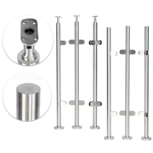
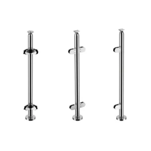
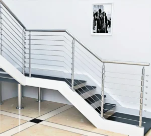
Post position is checked against the approved geometry: spacing along the run, offset from the edge or face, plumb, and squareness relative to the guard line. Viewrail’s install guide for its Express level surface-mount cable railing sets out this sequence for that system — work from the project layout drawing for post locations, orientation and rail lengths, confirm the posts are in line, square and plumb, and only then position the handrail brackets, with corner brackets facing the direction the guide specifies. The sequence is instructive beyond that one product: post geometry is verified independently, because a bracket cannot correct a post that is in the wrong place, and a correctly placed post can still carry a bracket turned the wrong way.
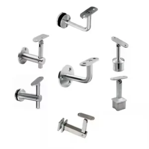
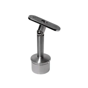
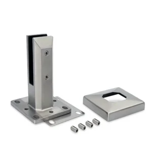
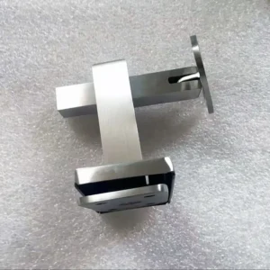
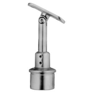
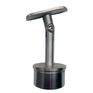
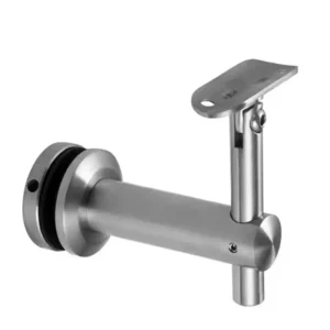
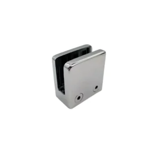
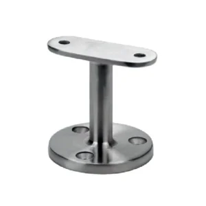
Bracket and saddle orientation is the second check, made at the affected location and considered on its own. A saddle rotated a few degrees on a round post, or a corner bracket installed facing the wrong way, throws the rail off its intended line while leaving every post exactly where the drawing put it. The clue is usually local: the deviation starts and ends at one fitting rather than growing along the run. Adjustable post handrail fittings widen the range of rail angle and height a given post position can accept, which is useful at stair-to-landing transitions, but adjustment range is a means of absorbing geometry, not evidence that the underlying geometry is right.
The third check is post-to-substrate movement, and it must be kept out of the fit discussion entirely. Push and pull the post at rail height and watch the base, the anchors and the surrounding substrate rather than the rail. If there is movement there, you are no longer diagnosing a component mismatch — you are looking at anchorage or structure, and the rail geometry downstream of that post cannot be trusted or corrected until the movement is resolved. Confusing the two wastes effort at best, and at worst hides a load-path problem behind a cosmetic adjustment.
Rail Profile, Saddle, and Connector Fit
Once post position and bracket orientation are accounted for, work along the rail itself in a fixed order: profile and straightness, then seating in the saddle, then each connector joint. Each of these can produce a visible misalignment, and each has its own tell.
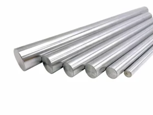
Start with the rail profile. Check that the supplied tube matches the specified outside diameter or section and wall, and that the piece is straight and round rather than drawn out of shape by handling, transport or a tight bend. Where the specification calls for it, ISO 1127, which sets dimensions, tolerances and conventional masses for stainless-steel tubes, gives a dimensional reference you can check the supplied tube against when that standard applies to the tube in question. That is a dimensional comparison only: it tells you whether the section is within the dimensional terms you ordered, and says nothing about the installed railing’s load capacity, finish, weld quality or compliance with project code.
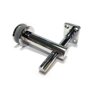
Next, look at how the rail sits in each saddle or bracket. The rail should bed down fully on the saddle face with even contact, and the fixing should pull it in without springing it sideways. A rail that rocks on a saddle, or that only touches at one edge, shifts as soon as it is clamped, and every downstream bracket inherits that shift. Trex’s ADA-compliant handrail guide for its own deck system makes the same distinction a useful one: that build calls for the rail to be fully inserted and for brackets to sit flush without wobble, with mounts aligned to the rail angle and post mounts lined up with elbows before fixing. Those checks belong to the demonstrated Trex build and its stated project and local requirements, but the principle of confirming seating and angle agreement before attachment transfers as a diagnostic habit.
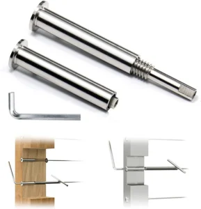
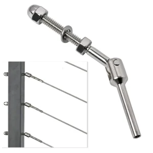
Then take the connectors. Rail-to-rail connectors, elbows and intermediate post handrail connectors have to seat at their mating ends; a joint that has pulled apart, bottomed out early on a burr, or been forced onto an out-of-round tube end will hold the two rail segments at a slight angle to each other. Look at the gap around the joint rather than at the rail a meter away — an open gap on one side, or a bright witness mark where the tube has been driven in off-axis, points to the joint as the origin of the kink.
The reason to keep the order is that each interface masks the one after it. A bowed tube makes saddle contact look wrong; a poorly seated saddle makes the next connector look misaligned. Working from the component outward, you find the first interface where the geometry departs from the drawing, and that is the one worth correcting.
Site Conditions That Require Separate Engineering Review
Some findings are not alignment problems at all, and they stop field correction rather than guide it. Movement at the post base that does not resolve when fixings are checked, anchors that have loosened or pulled in their substrate, cracked or spalled concrete around a base plate, an unexpected substrate such as thin topping over a void, or any condition that changes how guard loads travel from the rail into the structure, belongs to the project designer.
The reason for the boundary is that these conditions affect the load path, not the appearance of the line. A handrail that looks straight but sits on a post whose anchorage is in question has not been improved by alignment work. Equally, correcting geometry by packing shims, relocating anchors into fresh holes or re-drilling close to a slab edge changes edge distances and fixing performance, and those are engineering decisions tied to the substrate and the specified anchor, not field judgments.
The same applies where the investigation shows that the approved geometry cannot be achieved as drawn — posts set at a spacing the drawing does not allow, a stair pitch that differs from the one the shop drawings assume, or a transition where no available adjustment range closes the gap. Write down what you found, including the measurements and the pattern across the run, and pass it to the project designer with the question stated plainly. Whether the installed condition can be accepted, corrected in place, or needs re-detailing is decided by the project’s approved procedure and its designated approver, not by a general field fix applied across the job.
Correction Evidence Before Handover
| Evidence item | What the record should show | Limite de decisão |
|---|---|---|
| Geometry comparison | Installed rail centerline and elevations compared with the approved shop drawings | Confirms the measured relationship to approved geometry; it does not by itself establish root cause. |
| Interface finding | Whether the visible offset was traced to post position, bracket orientation, rail profile, or a connector joint | Distinguishes the affected interface from other interfaces that can create a similar symptom. |
| Movement separation | Rail-to-post fit and post-to-substrate movement recorded separately | Keeps a component mismatch separate from an anchorage or structural concern. |
| Deviation pattern | Locations and directions of deviations across level, stair, or ramp runs | A repeated direction can guide further investigation but does not prove cause. |
| Revisão de engenharia | Project-designer review of unresolved movement, load-path concerns, or substrate conditions | Records the project-specific decision rather than presenting a universal field fix. |
| Dimensional reference, when applicable | The stainless-steel tube dimensions or tolerances checked against ISO 1127 | ISO 1127 does not establish railing load capacity, finish, weld quality, or project-code compliance. |
The handover record should let someone who was not on site reconstruct what was measured, which interface was found responsible, what was changed, and what was escalated. That record is what distinguishes a documented correction from a rail that was simply nudged into looking right.
Keep the geometry comparison and the interface finding as two separate entries. The geometry comparison shows the installed centerline and elevations against the approved shop drawings, which fixes the measured relationship to approved geometry but does not on its own name a cause. The interface finding states where the offset was traced to — post position, bracket or saddle orientation, rail profile, or a connector joint — and that is the entry a reviewer uses to judge whether the correction addressed the right thing. Keeping rail-to-post fit separate from post-to-substrate movement in the record preserves the same distinction after the work is covered up.
Pattern evidence is worth recording in full, not summarized as “corrected.” The locations and directions of deviations across level, stair and ramp runs let the project team see whether the problem was local to one fitting or systematic across the run, which matters if a similar symptom appears elsewhere on the job. Where a dimensional check against ISO 1127 was made on supplied tube, note what was compared and keep it labeled as a dimensional check, since it carries no information about load capacity, finish, weld quality or project-code compliance.
Finally, record the engineering review itself: what was referred to the project designer, when, and what decision came back. Unresolved movement, load-path concerns and substrate conditions should appear in the handover file as project-specific decisions with the designer’s response attached, rather than as a note that something was adjusted on site.
For the supplier side of that conversation — whether a component mismatch is the cause and what replacement or adjustable fitting suits — have the approved shop drawings with the rail centerline and elevations, the measured deviations and their directions along the run, the post spacing and substrate type at the affected locations, the rail section and specified stainless grade and finish, and photographs of the fitting or joint where the offset begins.
Perguntas frequentes
P: When should corrective work on a misaligned handrail be paused?
A: Pause before changing brackets or cutting components until the installed centerline and elevations have been compared with the approved shop drawings and the affected interface has been isolated. Unresolved movement, load-path concerns, or substrate conditions require project-designer review before a field correction is selected.
P: How can the team tell whether the problem is local or affects the wider handrail run?
A: Record each deviation’s location and direction across the level, stair, or ramp run. A deviation concentrated at one saddle, bracket, rail profile, or connector joint supports a focused interface check, while a repeated direction across several locations helps the team identify where to investigate next; neither pattern alone proves the root cause.
P: What information should be assembled before a handrail alignment inspection?
A: Bring the approved shop drawings, measured rail centerlines and elevations, marked locations of visible offsets, and observations of post position, bracket orientation, rail profile, and connector fit. Record rail-to-post fit separately from any post-to-substrate movement so the team does not treat an anchorage or structural concern as a component mismatch.
P: Can an adjustable bracket or connector be used immediately to bring the rail back into line?
A: Only after the team has confirmed that the visible offset begins at that connection and has ruled out post-position and post-to-substrate movement concerns. Adjustment should follow the approved geometry and project-specific correction decision rather than be used to conceal an unresolved condition elsewhere in the assembly.
P: Does a tube check against ISO 1127 establish that the installed handrail is acceptable?
A: No. ISO 1127 can provide a dimensional reference for stainless-steel tube dimensions and tolerances when applicable, but it does not establish railing load capacity, finish, weld quality, or compliance with the project’s code and acceptance requirements. Those items need their own project-specific evidence.