Where does a continuous handrail actually begin and end, and what happens at every point where a stair meets a ramp, a ramp meets a landing, or a run meets a wall? These are not finish questions. They determine whether the handrail can be fabricated as a coordinated system or only as a set of separately detailed segments that happen to share a profile.
Route mapping across stairs, ramps, and landings
A continuous handrail is a routing decision before it is a fabrication decision. Treating stairs, ramps, and landings as one linked route, rather than as separate runs to be detailed later, exposes where the path actually changes direction, where it is interrupted by an opening or a structural condition, and where it must terminate. This mapping has to happen before brackets, returns, or lengths are finalized, because every downstream decision depends on knowing how the runs connect.
The reason this sequencing matters is that a handrail run is not an independent object; it is a segment of a route whose geometry is set by the stair, ramp, and landing conditions it passes through. A stair flight that lands into a ramp will force a transition in slope and possibly in rail height relative to the walking surface. A landing inserted between two flights may call for the rail to continue unbroken across it, or it may introduce a termination point if the route does not continue in the same direction. Where the project treats each flight, ramp segment, or landing as a separate design exercise, these connections tend to surface only during fabrication or installation, which is precisely the condition a linked route drawing is meant to avoid.
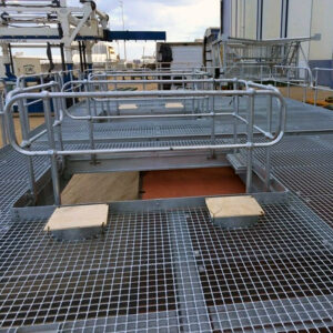
The practical consequence is that route mapping should be drawn, not assumed. A plan or elevation that shows the stairs, ramps, and landings as one continuous line, annotated at every point where the line bends, breaks, or ends, gives the fabricator and the installer a single reference for what “continuous” means on this project. Where the route is simple — one flight, one landing, one wall — this drawing step is brief. Where the circulation path involves multiple flights, direction changes, or mixed stair-and-ramp conditions, the same drawing step becomes the only reliable way to confirm that the handrail, as designed, is actually one continuous system rather than a series of runs that will be fabricated and installed as if it were.
This is also the stage at which the buyer should identify every point along the route that needs separate resolution later: each interruption, each change of direction, and each termination. Those points are not yet solved by the route map; they are only located by it.
Continuity breaks and transition points to resolve
| Route condition | What the coordinated drawing should show | Decisão apoiada |
|---|---|---|
| Interruption between linked runs | The location of the break and how the adjoining runs relate | Whether the planned route has an unresolved continuity break |
| Change of direction | The transition geometry connecting the approaching and departing runs | Whether the direction change is resolved for fabrication |
| Termination point | The end location and the applicable return or extension condition | Whether the run can end as drawn under the governing project requirements |
Once the route is mapped, each location flagged on it needs its own coordination before fabrication can proceed. Not every point on a continuous handrail route behaves the same way, and treating them as equivalent is where coordination gaps appear.
An interruption between linked runs — an opening, a structural element, or a gap in the wall or guard condition — breaks physical continuity even where the design intends one continuous rail. The question is not only where the break occurs, but how the two adjoining runs are meant to relate across it: whether the rail is meant to read as continuous in function even if it is not continuous in material, or whether the break itself is an accepted part of the design. A change of direction is a different kind of event. It does not interrupt the rail, but it requires a transition geometry that connects the approaching run to the departing run smoothly enough that a hand moving along the rail does not encounter a discontinuity in grip or height. A termination point is different again: it is not a condition to be bridged but a condition to be resolved, since the end of a run raises the return or extension condition that applies at that specific location.
The reason these three conditions need separate treatment is that each one changes what the coordinated drawing must show. An interruption needs the relationship between the two adjoining runs documented, not just the gap itself. A direction change needs the transition geometry, not just the angle. A termination needs the applicable return or extension condition confirmed against the governing project requirements, not just an end point marked on a plan. Where a project drawing shows a termination without specifying which return or extension condition applies, the fabrication question remains open regardless of how complete the rest of the route appears.
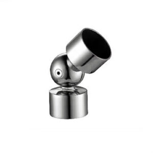
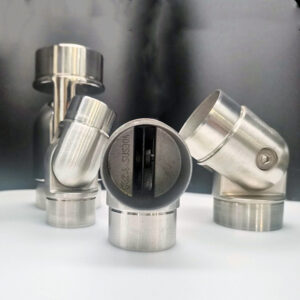
This is where seamless handrail connections become a relevant design choice at interruption and direction-change points, since the method used to join adjoining runs affects whether the rail reads as continuous once installed. Confirming which of these three conditions applies at each flagged point, and what the drawing shows for it, is what allows the route map from the previous section to convert into a fabrication-ready set of details.
Return geometry at walls, corners, and circulation edges
| Site condition | Questão de coordenação | Decisão apoiada |
|---|---|---|
| Wall buildup | Does the return geometry match the finished wall condition and rail-to-wall interface? | Whether the return can be detailed for the installed wall condition |
| Corner condition | How does the rail change direction or terminate at the actual corner? | Whether the corner geometry is resolved before fabrication |
| Adjacent circulation space | Where does the return sit relative to the adjoining circulation area? | Whether its installed position has been coordinated with that space |
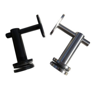
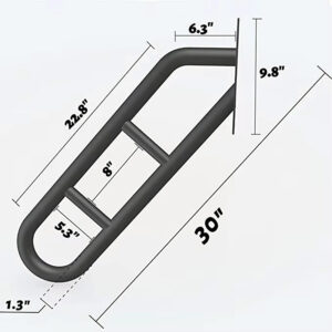
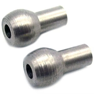
A return is not a standalone fitting; it is the point where the handrail route meets a physical condition that the fitting alone cannot resolve. The same end fitting, selected from a catalog, can produce a correctly detailed return in one wall condition and an unresolved interface in another, because the fitting’s geometry has to be coordinated with what it is returning into.
Wall buildup is the clearest case. A return at a wall depends on the finished wall condition — its thickness, its surface, and the rail-to-wall interface it creates — not on the nominal dimension of the fitting itself. Where the wall buildup is confirmed before the return is detailed, the fitting can be matched to the installed condition. Where it is not, the return risks being detailed against an assumed wall condition that differs from what gets built. The same logic applies at corners: a corner is a specific site condition, and the way the rail changes direction or terminates there has to be drawn against the actual corner geometry, not against a generic assumption of how corners behave. A 90-degree rail corner fitting, for instance, resolves a particular corner geometry; it does not by itself confirm that the installed corner matches that geometry.
Adjacent circulation space adds a third coordination layer. A return’s installed position has to be checked against the circulation area it sits beside, because a return that is correctly detailed in isolation can still conflict with the space available for people moving through that area. This is a site condition, not a fitting attribute, and it has to be confirmed against the actual layout rather than inferred from the return’s dimensions alone.
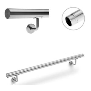
The common thread across these three conditions is that a return cannot be verified from a product page or a fitting specification alone. Sistemas de corrimão de parede contínua are designed to carry a route through these conditions, but the installed interface — wall buildup, corner geometry, circulation clearance — is a site-specific confirmation that sits outside the fitting itself. Where the buyer treats the return as resolved once a fitting is selected, the installed condition may still require adjustment; where the site condition is confirmed first, the fitting selection becomes a much narrower decision.
Bracket and substrate interfaces behind each run
| Project input | What it affects | Limite de decisão |
|---|---|---|
| Rail profile | Bracket fit and the basis for spacing | Check the layout for the selected profile |
| Substrato | The support condition at each attachment | Match the layout to the actual substrate |
| Projeto de conexão | How the rail, bracket, and substrate interfaces are detailed | Do not infer the connection from the bracket alone |
| Project loads | The basis for bracket selection and spacing | Use the project’s load criteria rather than a universal layout |
| Governing code | The provisions applied to bracket selection and spacing | Use the requirements adopted for the project |
Bracket selection and spacing are often treated as a layout exercise, but the layout is only valid for the specific combination of inputs that produced it. Changing any one of those inputs changes what the correct bracket layout is, which is why a universal spacing pattern cannot be assumed to carry across runs or projects.
The rail profile sets the basis for bracket fit and spacing because the bracket has to physically match the rail it supports; a different profile changes the attachment geometry even if the nominal rail diameter looks similar. The substrate behind each run changes the support condition at every attachment point — a solid wall, a stud wall, or a different backing condition each present a different capacity to receive a bracket, and the layout has to be matched to the substrate that is actually present, not assumed from the rail profile alone. Projeto de conexão is a separate layer again: how the rail, the bracket, and the substrate interface are detailed together determines whether the assembly behaves as intended, and this detail cannot be inferred just from knowing which bracket was selected.
Project loads and the governing code sit above these physical inputs as the basis against which bracket selection and spacing are checked. A layout that looks adequate for the rail profile and substrate may still not satisfy the load criteria or the code provisions that apply to the specific project, because those criteria are set by the project’s use and jurisdiction, not by the hardware catalog. Where any of these five inputs changes — profile, substrate, connection design, loads, or code — the bracket layout has to be reassessed rather than carried over from a previous run or a previous project.
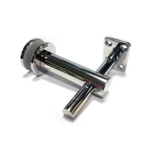
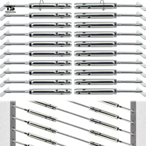
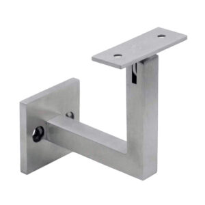
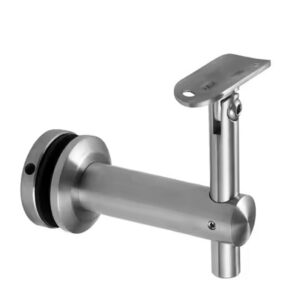
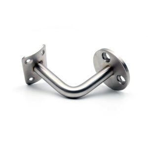
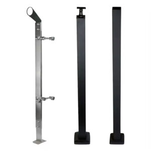
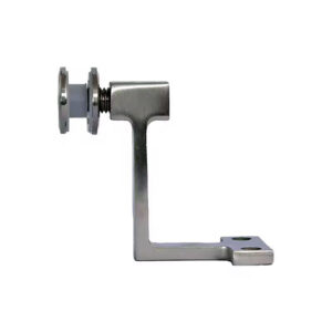
This is the point at which the buyer’s own project information becomes load-bearing in a literal sense: the rail profile, substrate conditions, and governing load and code requirements the buyer supplies are what allow a bracket layout to be evaluated for the specific installation, rather than compared against a generic spacing assumption. Adjustable handrail brackets are one response to uneven substrate or site conditions, but the adjustability of a bracket does not substitute for confirming the substrate and connection design it is being adjusted into.
Accessibility checks within the project’s governing scope
| Verificar | What to examine | Project decision |
|---|---|---|
| Project coverage | Whether the stair and handrail work falls within the applicable accessibility scope | Which adopted requirements govern the review |
| Continuidade | The handrail route through the covered stair and landing conditions | Whether continuity issues remain to be resolved |
| Folga na parede | The installed rail-to-wall condition | Whether the applicable clearance has been addressed |
| Gripping surface | The selected rail profile against the applicable gripping-surface provisions | Whether the profile satisfies the adopted project requirements |
| Extensões | The start and end geometry against the applicable extension provisions | Whether extension conditions remain to be resolved |
Accessibility provisions apply only where the project falls within their scope, and the first judgment a buyer needs to make is whether the stair and handrail work in question is covered at all before applying any specific provision to it. This scope question is separate from the technical provisions themselves, and skipping it produces the wrong kind of error: either applying requirements to a condition they do not govern, or assuming a condition is exempt when it is not.
For U.S. accessible means-of-egress stairs that do fall within scope, the Access Board Guide’s chapter on stairways sets out continuity, clearance, gripping-surface, and extension provisions for covered stair handrails. Continuity, in this context, is a check on whether the handrail route mapped earlier in the project actually continues through the covered stair and landing conditions without an unresolved gap. Clearance is a check on the installed rail-to-wall condition — the same wall buildup question raised in the return geometry discussion, now evaluated against a specific accessibility provision rather than against general return detailing. Gripping surface is a check on whether the selected rail profile satisfies the provisions that apply to covered stairs, which means the profile decision made for bracket and layout reasons also has to be evaluated against this separate criterion. Extensions are a check on the start and end geometry of the run — the termination points identified in the continuity-breaks section — against the specific extension provisions that apply where the project is covered.
The relationship between these checks and the rest of the article is direct: each one revisits a decision already made elsewhere — route continuity, wall clearance, rail profile, termination geometry — and re-evaluates it against a specific adopted requirement rather than against general coordination logic. Where the project is not within the accessibility scope described in the Access Board Guide, these specific provisions do not govern, though the underlying coordination questions about continuity, clearance, profile, and termination remain relevant on general design grounds. Confirming scope first, and then checking each provision against the adopted project requirements rather than against the guide’s general content, is what keeps this check from being applied incorrectly in either direction.
Fabrication release after dimensions and responsibilities are confirmed
Releasing a continuous handrail for fabrication is the point where every preceding judgment has to be closed out, not re-opened. The route has been mapped; each interruption, direction change, and termination has been resolved; return geometry has been matched to wall, corner, and circulation conditions; bracket layout has been checked against profile, substrate, connection design, loads, and code; and, where applicable, the accessibility provisions within the project’s governing scope have been checked. Fabrication release depends on these being confirmed, not assumed complete because the drawing looks finished.
The reason this matters as a distinct step is that a drawing can appear coordinated while still carrying an unconfirmed assumption in any one of these areas — a wall buildup that was estimated rather than measured, a substrate that was assumed rather than verified, a scope determination that was never explicitly made. Fabrication converts the drawing into fixed material and fixed geometry; it does not tolerate the same provisional reasoning that is acceptable during design development. This is also where project submittal information — drawings, material test certificates, load reports, and finish samples — functions as the record of what was actually confirmed, rather than as paperwork separate from the technical decisions already made.
Responsibility allocation follows the same logic as the technical confirmation. A supplier’s ability to fabricate hardware matched to the dimensions and conditions supplied does not establish that the supplier verified the wall buildup, confirmed the governing code, or determined accessibility scope; those confirmations rest with the parties who hold that site and project information. Where the buyer has supplied confirmed dimensions, confirmed substrate and loads, and a confirmed scope determination, fabrication can proceed against that information. Where any of these remain open, releasing for fabrication does not close the question — it only fixes the consequence of whichever assumption was carried forward unconfirmed.
Perguntas frequentes
P: What information should be confirmed before a continuous wall handrail is released for fabrication?
A: Confirm the linked route, dimensions, interruptions, changes of direction, termination conditions, and responsibility for unresolved interfaces. The drawings should also reflect the actual wall buildup, corners, circulation edges, rail profile, substrate, connection design, project loads, and governing requirements.
P: How should stairs, ramps, and landings be coordinated as one continuous handrail route?
A: Map them as linked runs and show how each run relates at interruptions, direction changes, and termination points. This makes unresolved continuity conditions visible before fabrication.
P: Is selecting a catalog end fitting enough to finalize a handrail return?
A: No. The return still has to be coordinated with the finished wall buildup, actual corner geometry, and adjacent circulation space so its installed interface and position are resolved.
P: What project details are needed to determine bracket selection and spacing?
A: Provide the selected rail profile, actual substrate, connection design, project load criteria, and governing code requirements. Bracket selection and spacing should be based on that combination rather than a universal layout.
P: When should accessibility provisions be checked for a handrail route?
A: First determine whether the route falls within the project’s applicable accessibility scope and which requirements have been adopted. For covered U.S. accessible means-of-egress stairs, review continuity, wall clearance, gripping surface, and extension conditions against those project requirements.