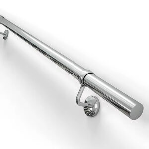
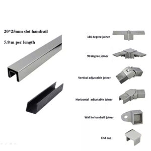
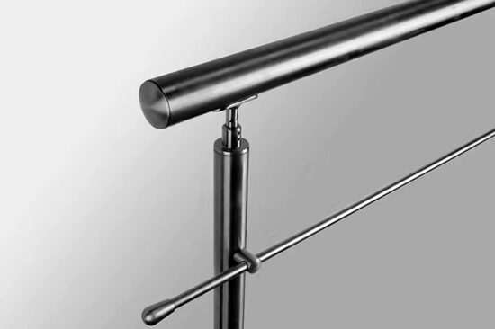
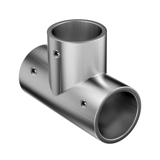
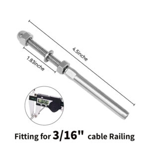
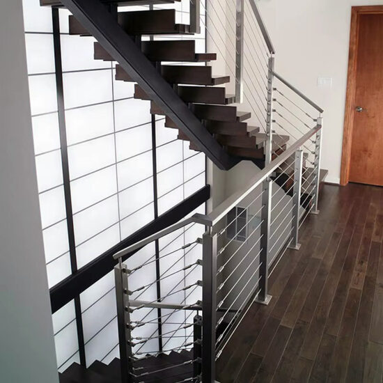
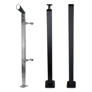
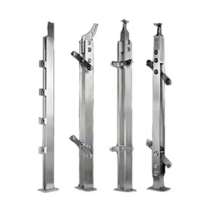
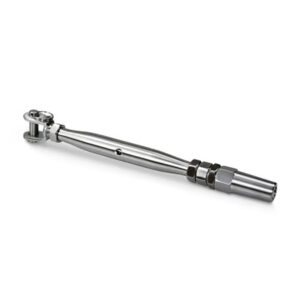
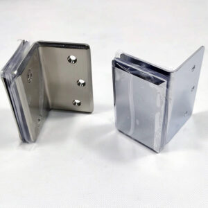
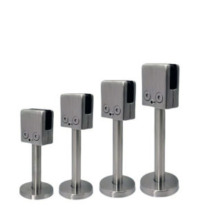
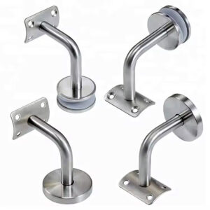
Wall brackets carry rail loads into the wall structure at fixed points, so a handover inspection has to confirm that what was installed matches what was approved, without overstating what a visual check can prove about concealed capacity. The question a project buyer or fabricator faces at this stage is not whether the brackets look acceptable, but which specific comparisons and records actually close out the punch list versus which items require separate confirmation from the anchor or structural side of the job.
Approved Drawings and Location Records Needed at Handover
A handover inspection is only as good as the reference it is checked against. Before any bracket is examined, the inspector needs the approved shop drawings for the run being reviewed, and a way to tie each bracket back to a specific, identified location on those drawings. Without that location record, a finding at handover has no fixed point to return to if remedial work is later required, and repeated defects across a run cannot be distinguished from a single isolated one.
The location record matters more where a project has multiple similar runs, similar bracket types, or repeated bracket spacing along a long wall. Where a run is short and brackets are few, a location reference may be as simple as a marked drawing. Where a run is long, involves transitions, or crosses different wall substrates, the location record needs enough detail that a second inspector, or the same inspector returning after remedial work, can find the exact bracket referenced without relying on memory or general description.
This is also the stage where the type of documentation available changes what the handover check can confirm. A specification structure such as UFGS 05 52 00 Metal Railings shows how a project-specific metal-railing specification and submittal package can be organized, but it functions as an example structure rather than a code the project is bound to or a requirement ESANG’s products are certified against. What matters for handover is not whether the project used that structure, but whether the project’s own approved drawings and submittals define the bracket line, projection, and location clearly enough to check against. If the approved documentation is silent on a dimension the field condition raises, that gap is itself a finding to record, not something the inspector should resolve by judgment on site.
Buyers sourcing wall mount brackets for a project should confirm, before handover begins, that the drawing set available to the inspection team is the current approved version and that it identifies bracket locations in a way consistent with how the project will track remedial work afterward. Where that alignment is missing, the checks that follow have less to compare against.
Alignment, Projection, Clearance, and Rail Continuity Checks
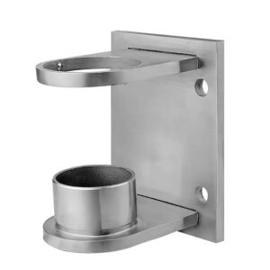
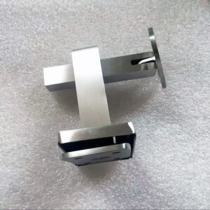
With the drawing basis and location records in place, the core handover comparison is straightforward in principle: bracket line, projection from the wall, clearance behind the rail, and continuity of the rail across brackets are all measured or observed against the approved drawings at each identified location. These four items are grouped together because they represent one comparison repeated at each point, not four separate judgments.
Line and projection determine whether the rail sits where the drawing places it and stands out from the wall by the distance the drawing specifies. A deviation at one bracket can be a localized installation issue; the same deviation repeated at several brackets along a run suggests a setting-out or template issue that affects the whole run rather than one fixing point. The distinction matters for how the finding gets closed: an isolated deviation may be corrected at that bracket, while a repeated deviation may require checking the method used to set brackets across the entire run before remedial work begins.
Clearance behind the rail affects hand and grip space and also interacts with wall-mounted obstructions the drawing may not have anticipated. Where clearance is tight against the approved minimum, even a small installation variance can bring the finished condition outside what was approved, so this check benefits from being made at each location rather than sampled.
Rail continuity across brackets is checked for consistent alignment from one bracket to the next, since a rail can satisfy line and projection at each individual bracket while still showing a visible break or twist between them. This is a condition where checking brackets in isolation would miss the defect entirely; the check has to include the transition between adjacent brackets, not just the bracket points themselves.
Where a drawing calls for a particular projection or clearance and the field condition cannot achieve it because of an unanticipated obstruction, that is a finding for the project team to resolve against the approved drawing, not a deviation the field inspection should approve on its own judgment.
Finish Direction, Surface Damage, Staining, and Cleaning Condition
| Visible condition | Handover comparison | Evidence boundary |
|---|---|---|
| Finish direction | Compare the visible face with the agreed finish direction. | This check addresses visible finish condition. |
| Staining, scratches, and fabrication marks | Assess the visible condition under the project’s acceptance conditions and identify the affected location. | Visual handover does not establish structural performance. |
| Incomplete cleaning | Assess the visible condition under the project’s acceptance conditions; ASTM A380/A380M-25 may inform cleaning and surface-treatment scope. | That scope does not qualify weld strength or structural performance. |
Finish inspection at handover is a visible-condition check, and keeping it framed that way avoids drawing conclusions the check cannot support. The visible face of the bracket is compared against the finish direction the project agreed to, and any staining, scratching, or fabrication marks are assessed under the project’s own acceptance conditions rather than a general standard of appearance.
Finish direction matters because brushed or directional finishes read differently depending on the angle of light and the direction the grain runs; a bracket installed with its finish direction rotated from the rest of the run can be visually correct in isolation and still inconsistent with adjoining hardware. This is a comparison that has to be made against the specific run, not against a general expectation of what the finish should look like.
Staining, scratches, and fabrication marks are recorded by location so that a pattern across multiple brackets can be separated from a mark on one unit. A scratch on a single bracket may be an installation or handling issue at that point; the same mark appearing at several brackets suggests a condition introduced earlier, during fabrication or transport, that the project team needs to trace back rather than treat as a series of unrelated field defects.
Incomplete cleaning is also a visible condition, and where cleaning or surface-treatment questions arise, ASTM A380/A380M-25 addresses surface-contaminant removal, weld-area treatment, and methods for assessing stainless-surface cleanliness. That scope covers cleaning and surface treatment; it does not extend to weld strength or structural performance, so a cleaning-related observation at handover should not be read as evidence about the structural condition of a weld even where the same area shows both a cleanliness issue and a visible mark.
Visible Fixing Hardware and the Limits of a Visual Check
Fixing hardware inspection at handover has one clear boundary: the inspector can confirm that the specified fixing hardware is present, appears seated, and is documented where it remains visible, but a visual check cannot establish the capacity of a concealed anchor. This distinction changes what the finding at this stage can support and what it cannot.
Presence and seating are observable conditions. Where a bracket calls for a specific fixing type, the inspector can confirm that type is what was installed, that it appears fully seated rather than proud or loose at the surface, and that this observation is recorded against the bracket’s location. Where fixing hardware is concealed behind a cover plate or within the wall assembly, the visual check is limited to whatever remains exposed, and the concealed portion is outside what this inspection step can confirm.
This limitation matters most where the wall substrate or anchor type is one where field performance depends on installation details that are not visible after the fact, such as anchor embedment or torque applied during setting. A bracket that looks correctly fixed from a visual check can still have a concealed anchor condition the check does not reach; conversely, a bracket that has minor visible surface irregularity at the fixing point is not automatically an indication of a concealed problem. Neither condition can be resolved by the visual check alone.
Where a project needs assurance beyond what a visual check provides, that assurance has to come from a separate verification step defined by the project, not from extending the conclusions of the handover visual inspection. The handover record should state plainly what was and was not checked, so that the punch list does not later get read as though it closed a question it was never positioned to answer.
Bracket-to-Rail Fit and Project-Approved Movement Checks
The fit between bracket and rail is checked for how the two components engage at their interface, and any movement is assessed only through whatever check the project has approved for that purpose, rather than through a generic field test applied uniformly regardless of what the project specified.
Fit at the bracket-to-rail interface can vary depending on how the two components are designed to engage: some interfaces rely on a clamped or mechanical connection, others on a fitted sleeve or collar condition. The inspection records how the fit appears at each location, and where the project has defined a specific movement check appropriate to that interface type, the result of that check is recorded against the same location. Substituting a different test, or applying one interface’s check to a different interface type, would not produce a comparable result across the run.
Where movement is found, the record should capture what was found and any remedial work performed, without extending that finding into a conclusion the project-approved check was not designed to support. A movement check appropriate to one fixing method does not necessarily indicate the same thing about a different fixing method elsewhere in the same project, so a finding at one location should not be generalized to other locations using a different interface without checking them individually.
This section of the handover record also connects to the anchoring and fastener judgments that affect the surrounding railing system, since bracket-to-rail fit interacts with how load is transferred into the wall through the fixing hardware. Where fit or movement findings suggest an interface condition beyond what remedial work at the bracket can resolve, that finding should be carried forward to whoever holds responsibility for the anchorage design, rather than closed out solely within the punch list.
Punch-List Evidence for Closing Repeated and Isolated Defects
| Punch-list evidence | Use during closeout |
|---|---|
| Identified location | Tie the finding and any recorded remedial work to the place inspected. |
| Photo reference | Connect the visible condition to its location record. |
| Finding pattern | Separate repeated alignment or finish defects from isolated damage. |
Closing a punch list at handover depends on being able to tell whether a given finding is isolated to one bracket or repeated across a pattern of brackets, and that distinction depends on the quality of the evidence recorded at each location rather than on judgment applied after the fact.
An identified location ties each finding, and any remedial work recorded against it, back to the specific point inspected. Without that tie, a finding recorded generically for “the run” cannot later be matched to confirm that the correct bracket was repaired, or to confirm that a bracket flagged for one issue was not also carrying a second, unrelated issue that gets lost when the record is closed as a single line item.
A photo reference connects the visible condition to its location record, and this matters particularly for finish and surface conditions that can otherwise be difficult to describe precisely in text, or that a later reviewer might interpret differently from how the original inspector saw the condition. Photo evidence also supports comparison if a remedial action is disputed, since it fixes what the surface looked like at the time of the original finding rather than relying on a written description alone.
The finding pattern across locations is what allows a repeated alignment or finish defect to be separated from isolated damage. A single scratched bracket in an otherwise consistent run reads differently from the same mark appearing at multiple brackets along the run; the first suggests a localized handling issue, and the second suggests a condition introduced earlier in fabrication, transport, or installation method that affects more than the one bracket flagged. Where evidence is recorded by location and supported by photo reference, this pattern becomes visible directly from the punch-list record itself. Where evidence is recorded only as a general note that “some brackets” showed an issue, the pattern is lost, and the closeout cannot distinguish whether the underlying cause was addressed or whether only the single reported instance was corrected.
Frequently Asked Questions
Q: What should be settled before the handover inspection begins?
A: Use the approved shop drawings and project acceptance conditions as the comparison basis. Confirm the drawing set, identified inspection locations, and photo-reference method before the walkdown so each finding can be tied to the right place and requirement.
Q: Can a visual fixing check confirm concealed anchor capacity?
A: No. The inspection can confirm that the specified hardware is visibly present and seated, but it cannot establish concealed anchor capacity. Treat visible condition and connection capacity as separate acceptance items, and identify the project evidence required for the concealed connection.
Q: How should movement found during handover be handled?
A: Record only the result of the project-approved check at the identified location, together with any remedial work. Do not convert that observation into a universal pass/fail threshold or use it as proof of concealed connection capacity.
Q: Does a cleaning or surface-treatment reference establish structural acceptance?
A: No. ASTM A380/A380M-25 may inform cleaning and surface-treatment scope, but it does not qualify weld strength or structural performance. Close the visible finish item under the project acceptance conditions and verify structural performance against the separate project evidence.