Bracket layout problems rarely surface until installation is already underway — and when they do, the fix usually requires pulling brackets, repatching walls, and reordering hardware on a timeline that stalls the broader stair finish. The specific failure pattern that causes this most often is trusting the elevation drawing as a complete picture of the stair run, when the actual wall conditions — stud spacing, substrate transitions, landing geometry, finish buildup — have already shifted the viable anchor points enough to break rail continuity or push bracket spacing past the threshold where the run remains structurally defensible. That gap between the drawing and the field condition is a procurement and layout problem, not just an installation problem, which means the decisions that prevent it have to be made before hardware is ordered. What follows gives installers and specifiers a practical framework for evaluating stair runs, choosing between fixed and adjustable hardware, and detailing transitions in a way that holds up under both inspection and load.
What should be checked on the stair run before brackets are ordered
The elevation drawing establishes the stair pitch and the nominal rail height, but it rarely captures the conditions that actually control bracket placement. Wall build-up from framing tolerances, drywall thickness variation, tile or stone cladding, and base trim can collectively shift the rail line by enough to move a bracket out of stud range — and that shift is invisible until someone physically strings a line across the run.
A five-point field check before ordering resolves most of this. Confirm the stair pitch directly, since even a small deviation from the design angle changes where the first and last brackets land relative to nosings and landings. Mark stud locations along the full run — not just at the intended bracket positions — because stud spacing on site-built stairs is often irregular enough that a fixed bracket layout will land at least one anchor in a hollow zone. Check the hand clearance envelope between the finished wall surface and the intended rail centerline; finish layers added after framing can compress that clearance below what graspability requires on accessible routes. Note any nosing or finish buildup that might alter the effective rail height at individual treads. Finally, verify the rail endpoint positions, since brackets need to land within 12 inches of each end of the handrail run to prevent terminal movement and maintain anchoring integrity at the most structurally exposed positions.
Two of the most consequential layout thresholds — maximum bracket spacing and end placement — can be summarized as design inputs that govern the bracket count and distribution before a single hole is drilled.
| Checkpoint | Requirement | Why It Matters |
|---|---|---|
| Maximum bracket spacing | 48 inches maximum | Prevents sagging and ensures code compliance for stability. |
| End bracket placement | Within 12 inches of each handrail end | Ensures secure anchoring and prevents rail movement at termination points. |
Exceeding 48-inch spacing between brackets creates a sag condition that becomes more pronounced under lateral load, particularly on longer runs where mid-span deflection compounds. That figure is a widely applied layout threshold in handrail practice, grounded in structural stability, though the specific authority governing a given project may impose tighter spacing depending on rail profile and material. OSHA 1926.1052 establishes that handrail systems in construction contexts must be structurally sound and capable of withstanding specified loads — the bracket spacing discipline that achieves that standard is a layout input, not a detail to resolve in the field.
How landings and return bends change bracket placement
Landings are where the stair geometry stops being linear, and that transition compresses three separate bracket placement problems into one confined area: the angle changes, the extension requirement begins or ends, and wall anchor access may be limited by framing at the landing platform.
On a straight run, bracket placement follows a repeating pattern that can be pre-planned and prefabricated with reasonable confidence. At a landing, the bracket immediately before the angle change has to absorb the transition from the inclined run to the horizontal extension, and the bracket after it has to re-establish the correct rail height and angle for the next run. When a return bend is involved, the geometry at that connection point means the last bracket on the inclined section and the first bracket on the horizontal extension are often closer together than the standard spacing logic would place them — which is acceptable for continuity but requires explicit layout, not an assumption that standard spacing carries through automatically.
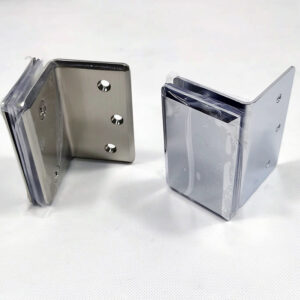
The fixed-versus-adjustable bracket decision becomes a real engineering trade-off here. A fixed bracket with a set mounting angle has no tolerance for the variation in wall angle that routinely appears at landing framing junctions. Adjustable brackets with a wide angular range — some products accommodate something approaching 0° to 270° of rotation, though the actual range varies by product — can absorb those transitions without requiring a custom fitting or a bracket order revision. That flexibility has a cost in procurement complexity and sometimes in load rating, so the decision should be evaluated against how well the landing geometry is confirmed before installation begins, not made as a default in either direction.
Where clearance and anchoring conflicts usually appear
Most clearance and anchoring conflicts follow a predictable distribution along the stair run. The first and last brackets near the landings carry the highest anchoring demand and often face the most constrained wall framing. Mid-run brackets over stud gaps are the most likely to be installed into hollow wall zones when layout is done by spacing alone rather than by stud verification. And bracket positions near wall obstructions — electrical boxes, conduit runs, structural blocking — often get shifted without compensating adjustments to adjacent brackets, which quietly pushes the spacing past threshold.
The hollow-wall anchoring failure is the one most likely to pass visual inspection and still fail under load. A bracket fastened into drywall without stud engagement can look and feel secure during installation — the fastener seats cleanly, the bracket doesn’t move when hand-tested — and still pull out under the lateral load of someone catching their fall on the rail. That failure mode is most common when bracket layout is finalized from spacing math alone and stud positions are checked after the fact rather than before. Resolving stud location first, then finalizing bracket spacing to align with available anchoring, is the sequencing that prevents it.
Hand clearance conflicts tend to appear specifically at wall returns, at corner bracket positions, and wherever finish cladding was added after the initial rail height was planned. The Access Board guidance on accessible routes establishes that graspable surfaces require a minimum clear width between the rail and any adjacent wall surface — when finish layers compress that dimension, the compliance defensibility of the run is compromised in a way that may not be visible to a casual inspection but will surface during a formal accessibility review. Verifying actual clearance against the finished wall surface, not the framed surface, is a layout step that often gets deferred until it becomes expensive to correct.
Why adjustable hardware reduces stair-site rework
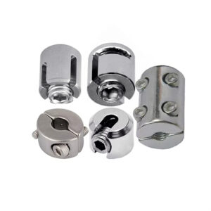
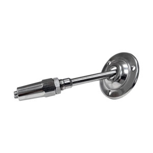
The rework case for adjustable brackets is strongest on renovation jobs, and it is not primarily about the angular flexibility — it is about substrate variation. A renovation stair run can pass through drywall, hit a section of masonry, continue past a stone veneer wall, and terminate at a wood-framed landing within a single flight. Each substrate has different anchoring requirements, different surface planes, and often slightly different wall offsets from the nominal framing line. A fixed bracket with a set projection and a fixed mounting plate has essentially no tolerance for those variations; every substrate transition becomes a custom fit that requires either a modified bracket or a shim and patch solution.
Adjustable wall handrail brackets designed for variable projection and angular adjustment absorb those substrate transitions without requiring individual bracket modification. That capability reduces on-site rework not because it eliminates the need for precise layout, but because it moves the accommodation from fabrication and patching to hardware adjustment — which is faster, cheaper, and reversible.
The procurement implication is that the cost comparison between fixed and adjustable systems should not be made on unit price alone. On a renovation job with confirmed mixed substrates, the rework hours on a fixed system commonly exceed the premium on adjustable hardware. On a new-construction job with verified wall geometry and consistent framing, that rework delta shrinks significantly, and the case for fixed brackets strengthens correspondingly. The decision is a site-condition judgment that has to be made at layout — after the field check, not before it.
How to detail transitions without losing continuity
Continuity failures at transitions are usually spacing failures in disguise. When the bracket immediately preceding a landing, return bend, or handrail termination is placed by standard spacing logic without accounting for the transition geometry, the result is either an unsupported span that exceeds the load-appropriate threshold or a bracket cluster that creates a clearance problem at the transition itself.
For runs longer than five feet, a three-bracket minimum — at each end and at least one mid-run position — is a useful planning baseline that ensures neither end is unsupported and that mid-span deflection is controlled. That criterion is a layout input derived from standard practice, not a formal regulatory mandate, and for runs with complex transitions, additional brackets at each transition point will typically be needed beyond that baseline count.
The transition detail that most often creates continuity problems is the extension at the bottom of a stair run. Horizontal extensions beyond the last riser require their own bracket support, and on wall-mounted handrail systems, the wall framing at the bottom landing may not provide anchor access at the position where a bracket is geometrically needed. Confirming anchor availability at extension endpoints before finalizing the bracket layout — and before the landing wall is finished — prevents a condition where the extension is either unsupported or supported by a fastener driven into unsuitable material.
Rail profile also interacts with continuity at transitions. Where a round or oval rail profile terminates into a return or wall-mounted fitting, the fitting geometry must be compatible with both the rail diameter and the bracket projection; mismatches in that detail often result in a visible alignment break at the transition that reflects poorly on the installation quality and may affect graspability on accessible routes. The Access Board’s guidance on accessible routes treats rail graspability and continuity as directly linked — a discontinuity in gripping surface at a transition is a compliance exposure, not just an aesthetic issue. Cross-referencing rail diameter and gripping surface requirements at the transition detail stage prevents late-stage fitting substitutions.
For context on how gripping surface standards interact with bracket and rail selection, the ADA-compliant stainless steel handrail diameter and gripping surface standards are worth confirming before hardware is specified, since they set the outer boundary on what rail profiles remain accessible through transitions.
When fixed bracket layouts are still safe to use
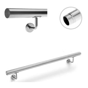
Fixed brackets are not a lesser choice — they are the appropriate choice under specific, verifiable conditions. When the stair geometry has been confirmed in the field, the wall substrate is consistent along the full run, stud positions are mapped and align with the planned bracket spacing, and the rail height and pitch are set before hardware is ordered, a fixed bracket layout simplifies prefabrication, reduces installation variables, and provides reliable long-term performance without the adjustment mechanism that adjustable hardware introduces.
The condition that has to be confirmed before committing to a fixed layout is that the wall plane is consistent. Even a modest offset between framing sections — common at stair sidewalls where the landing framing ties into the stair stringer framing — can produce a wall surface variation that a fixed bracket cannot accommodate without shimming or cutting. If that verification has been done and the wall is confirmed consistent, the fixed bracket is defensible and performs well. If it has not been done and the assumption is that new construction implies consistent geometry, that assumption will occasionally be wrong in ways that are discovered at installation.
The practical review check is: can the bracket spacing be fully resolved to confirmed stud locations before the hardware ships? If yes, and if the substrate is uniform, fixed brackets are a legitimate and often preferable choice. If the answer requires any qualification — “mostly studs,” “mostly consistent,” “we’ll adjust on site” — that qualification is the signal that adjustable hardware is the lower-risk option for that run.
Fixed bracket systems also simplify the handoff to inspection. A layout where every bracket position is documented against a confirmed stud location and a verified spacing interval is easier to defend during a site review than a field-adjusted layout where position decisions were made during installation. For projects where inspection documentation matters, that auditability is a meaningful advantage of the fixed-layout approach when conditions support it.
Bracket placement decisions have a longer tail than most installers expect. A spacing choice made from the drawing — without verifying studs, substrate transitions, or landing geometry — can hold for months before a load event reveals the anchoring gap. The decisions that matter are the ones made during layout: confirming anchor locations before spacing is finalized, verifying wall consistency before choosing between fixed and adjustable hardware, and treating transition details as bracket placement problems rather than fitting problems.
The concrete pre-procurement judgment is whether the site condition is controlled or variable. Controlled geometry with confirmed framing supports a fixed layout. Variable geometry — mixed substrates, renovation conditions, irregular framing, unconfirmed stud spacing — warrants adjustable hardware, and that determination should be documented at layout rather than left to installer discretion at installation. Getting that judgment right before the hardware order is placed is what separates a clean stair run from a rework scenario.
Frequently Asked Questions
Q: What happens if stud spacing along the stair run doesn’t align with the planned bracket positions?
A: Finalize bracket positions around confirmed stud locations — not the other way around. Spacing math that lands a bracket in a hollow zone produces an anchor that can feel secure during installation and still pull out under lateral load. Map every stud along the full run first, then distribute bracket spacing to match available anchoring. If the resulting spacing approaches or exceeds 48 inches at any point, add a bracket rather than accepting the gap.
Q: Does the fixed-versus-adjustable decision need to be made before hardware is ordered, or can it be resolved on site?
A: It must be made before ordering. The field conditions that determine which system is appropriate — substrate consistency, stud alignment, wall plane variation, landing geometry — are all knowable before procurement if the site is checked properly. Deferring that decision to installation means either arriving with hardware that doesn’t fit the condition or absorbing rework costs that exceed any savings from defaulting to the cheaper system upfront.
Q: Is adjustable hardware always the safer default on renovation jobs, even when the wall geometry looks consistent?
A: Not automatically, but the bar for confirming renovation geometry is higher than for new construction. A renovation wall that appears consistent can conceal substrate transitions, patched framing, and surface offsets that only become apparent once brackets are being set. Unless the full run — substrate type, wall plane, and stud locations — has been physically verified from end to end, adjustable hardware carries meaningfully less rework risk. Consistent-looking is not the same as confirmed consistent.
Q: How does finish cladding added after the initial rail height was planned affect compliance, not just fit?
A: It creates a graspability compliance exposure, not just a dimensional inconvenience. The Access Board guidance on accessible routes ties graspable surface requirements to the clear distance between the rail and the adjacent wall surface. Finish layers added after the rail height is set can compress that clearance below what an accessible route requires — and that gap won’t appear in a visual walk-through but will surface during a formal accessibility review. Clearance must be verified against the finished wall surface, not the framed one, before the layout is locked.
Q: For a project where inspection documentation is a contractual requirement, does hardware choice affect how defensible the bracket layout is during review?
A: Yes — a fixed layout tied to documented stud locations and verified spacing intervals is substantially easier to defend at inspection than a field-adjusted layout where position decisions were made during installation. If every bracket position is traceable to a confirmed anchor and a measured spacing interval recorded before installation, the layout has a clear audit trail. Adjustable hardware is the right choice when site conditions require it, but where geometry is confirmed and a fixed system is appropriate, that auditability is a concrete advantage worth factoring into the specification decision.