A submittal package that arrives after fabrication has already started is not a documentation formality — it is a rework trigger. Material test certificates tied to the wrong heat number, finish references that exist only as catalogue descriptions, and load reports without component-specific callouts can stall architect approval, customs clearance, and site installation release at the same time rather than sequentially. The sequencing failure is almost always the same: the project team treats document collection as a post-confirmation task rather than a pre-approval condition. Understanding which documents serve which evidentiary role — and what happens when each one arrives late or incomplete — is what allows a project buyer, specification team, or railing installer to hold the schedule rather than respond to it.
Submittal package contents before project approval
A submittal package does not function as a record — it functions as a fabrication license. Until every document is present and traceable to a specific component, fabrication should not proceed, because any gap discovered after cutting begins converts a paperwork problem into a dimensional one.
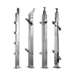
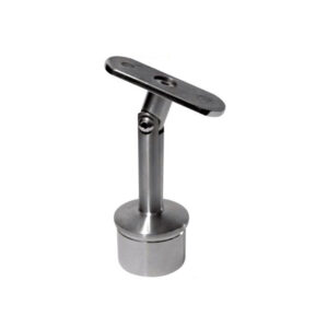
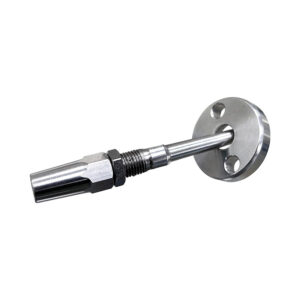
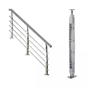
The drawing content is the load-bearing element of the package. Plan view, elevation, section and connection details, material callouts covering tube size, wall thickness, grade and finish, and weld symbols must all be present before the package is treated as complete. Omitting any of these at the drawing stage transfers the decision to the fabricator, who will either make an assumption or pause production — neither of which serves the project schedule. For wall-mounted systems specifically, bracket projection and wall clearance details must appear as dimensioned callouts on the bracket detail sheet, not as implied field conditions.
The dimensional figures in the table below — handrail height, baluster spacing, diameter, wall clearance — reflect widely referenced design thresholds drawn from standard practice. They are not presented here as governing regulatory requirements, since applicable code depends on jurisdiction, building type, and occupancy classification. What they do represent is the minimum specificity expected in a submittal drawing: if these values are left unspecified or ambiguous, an architect or building official reviewing the package has no defined basis for approval.
| Submittal Item | Specification / Requirement | Why It Matters |
|---|---|---|
| General drawing content | Plan view, elevation, section/connection details, material callouts (tube size, wall thickness, grade, finish), weld symbols | Ensures fabricator has complete specifications, avoiding rework |
| Handrail height | 34–38 inches from stair nosing | Code compliance, prevents design rejection |
| Baluster spacing | Maximum 4 inches | Safety compliance, avoids approval delays |
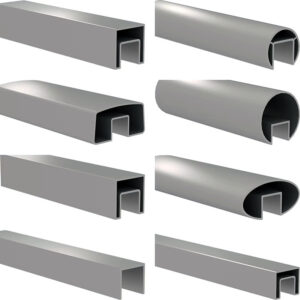
| Handrail diameter | 32–50 mm (42 mm recommended for graspability) | Ensures graspability and code compliance |
| Wall clearance (bracket) | 50–75 mm on bracket details | Ensures graspability, prevents installation issues |
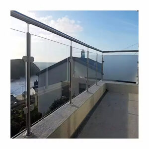
| Glass infill railing (if applicable) | Include load reports, glass thickness/type specifications | Ensures structural adequacy, prevents approval rejections for glass systems |
Glass infill railing configurations introduce a layer of complexity that a standard handrail submittal does not cover. Load reports and glass thickness or type specifications are required not because they complete the paperwork set, but because the structural calculations underlying a glass panel system cannot be inferred from the drawing geometry alone. Treating a glass infill submittal as structurally equivalent to a tube-and-baluster submittal is a planning error that typically surfaces during architect review rather than before it.
Drawings, MTCs, load reports, and finish samples as separate evidence
Each document type in the submittal package answers a different question, and conflating them is one of the more reliable ways to produce a package that looks complete but fails review.
The drawing answers what is being supplied and how it connects. The material test certificate (MTC) answers what the material actually is — its chemical composition, mechanical properties, and heat traceability. The load report, where required, answers whether the system as configured can carry the anticipated forces. The finish sample answers what the delivered surface will look like when installed. None of these documents substitutes for another, and a reviewer who accepts one in place of another is absorbing a risk that will typically surface during inspection, customs audit, or client sign-off.
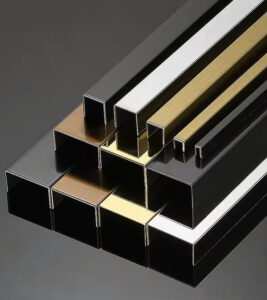
The finish sample point deserves specific attention because it is the document most often treated as optional until a dispute makes it essential. When a drawing references a finish by catalogue name or a generic descriptor — “brushed,” “mirror,” “satin” — without a physical reference sample, there is no shared standard between the supplier and the project team. Stainless steel finishes vary meaningfully across manufacturers in grit direction, reflectivity, and surface texture even when described identically. A physical sample, confirmed and archived before production, functions as the contractual baseline. Without it, finish disputes require a re-supply decision rather than a reference check. For insight into how material reports should be structured to support traceability across these document types, MTR documentation requirements provide a useful framing of what distinguishes a traceable certificate from a generic mill document.
MTCs require one additional qualification: the certificate must be linked to the specific heat or batch number covering the supplied components, not to a representative sample from a prior production run. A valid MTC format is a necessary condition, but heat-number correspondence is the verification step that makes it meaningful. This is where ISO 10474:2013 and EN 10204:2004 provide useful framing — both standards define inspection document types and the conditions under which they are issued, which gives buyers and specification teams a common vocabulary for requesting the correct document category rather than accepting whatever the supplier defaults to providing.
ASTM and ISO references that support hardware documentation
Standards references serve a documentation function in handrail submittals, not a fabrication or installation compliance function. Misapplying them — treating a document-type standard as a structural design rule, for example — creates false confidence without improving project outcomes.
ISO 10474:2013 defines inspection document types for steel and steel products. Its practical value in a handrail submittal context is that it gives buyers a defined framework for specifying which type of certificate they need — a distinction that matters when a supplier issues a works certificate but the project requires a specific inspection certificate issued by an independent body. Referencing the standard in a purchase order or submittal requirement forces a precise conversation about document type rather than leaving it open to supplier interpretation.
EN 10204:2004 covers the same territory with more granular document categories and is widely referenced in European-influenced specifications. When a project’s MTC requirement is stated only as “certificate required,” the supplier may default to the least demanding category. Specifying the document type explicitly — and citing the relevant standard — closes that ambiguity before production rather than during review. The ASTM and ISO standards compliance guide provides further detail on how these references map to hardware procurement decisions.
ISO 9001:2015 sits at a different level. It describes a quality management system framework, not a product or document requirement. Its relevance in a submittal context is that a supplier operating under a certified QMS has documented procedures for traceability, non-conformance control, and record retention — which reduces the probability that an MTC will be issued for the wrong heat number or that a finish sample will not be archived after approval. It is a credentialing reference, not a performance guarantee, and should be read as such when evaluating supplier capability rather than as a substitute for document verification.
Delay risks when material reports arrive after fabrication
The timing failure that most reliably compounds into a schedule event is not a single missing document — it is the pattern of treating document collection as a post-confirmation task. When material test certificates are requested after fabrication has started, any non-conformance they reveal cannot be corrected without scrapping or reworking material that has already been cut, bent, or welded. What was a preventable supplier conversation becomes a production restart.
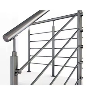
Drawing omissions follow a parallel dynamic. Stair pitch, raked-to-level transition details, and fixing specifications are the elements most frequently absent from concept-stage drawings, and each one becomes a hard stop the moment fabrication reaches the affected geometry. A stair pitch ignored in the drawing set produces a fabricated rail that does not fit the actual stair — a dimensional error that requires site modification or re-fabrication, not field adjustment. Transition details between raked rail and level landing rail, when omitted, leave the fabricator to interpret the connection independently, which creates a high probability that the fabricated component will conflict with the installed condition.
The compounding effect matters. A missing MTC that arrives after fabrication, drawing omissions that surface during shop drawing review, and a finish reference without a physical sample do not fail independently — they tend to surface together during the approval stage because they all originate from the same sequencing error. The table below maps the most common omissions against their consequences and the verification steps that prevent them from reaching the fabrication stage.
| Omission / Insufficient Detail | Consequence | What to Confirm |
|---|---|---|
| Missing or incorrect handrail details (dimensions, bracket locations, fixing types) | Stops entire project; schedule delays | Verify all dimensions, bracket locations, and fixing types are specified |
| Stair pitch ignored in drawings | Fabricated rail does not fit; rework and site modifications required | Confirm stair pitch angle is documented |
| Transition details between raked and level landing rail omitted | Fabricator confusion; fabrication errors and delays | Ensure transition connection details are clearly shown |
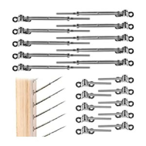
| Under-specified fixings (anchor bolts, base plates) | Structural risk; approval rejections or on‑site failures | Confirm fixing specifications are included in submittal |
| Wall clearance forgotten (typically 1.5 inches) | Handrail non‑installable due to bracket projection; installation delays | Verify bracket projection and wall clearance are detailed |
There is a trade-off worth naming explicitly: catalogue-only suppliers often move faster at the quote stage and appear lower-risk for straightforward replacement orders. For a project requiring a full submittal package, however, that speed advantage collapses the moment the architect or import reviewer asks for heat-traced MTCs, component-specific load references, or an archived finish sample. The project that appeared lower-risk based on quote turnaround becomes higher-risk once approval documentation is required.
Approval threshold after documents match the supplied components
A submittal package should be treated as conditionally incomplete until every requested document can be traced to a specific supplied component — not to the product range, not to the supplier’s standard grade, and not to a prior project. Partial document sets that appear complete at a glance are the version most likely to cause last-minute approval delays, because the gap is not visible until a reviewer attempts to cross-reference the certificate against the component.
Shop drawing review is the cross-reference step that makes this traceability possible. Before fabrication proceeds, the shop drawings must be checked against the original design intent to confirm that dimensions, connection details, material callouts, and fixing specifications align with what the submittal documents describe. This is not a broad quality regulation — it is a specific verification point with a defined output: confirmation that the document set and the fabricated scope are describing the same object. When this check is skipped or treated as a formality, the first mismatch surfaces on site rather than at the drawing stage, where correction is cheap, rather than during installation, where it is not.
CAD and BIM-based detailing reduces the probability of omissions reaching fabrication by making errors visible at the drawing stage — misaligned geometry, missing connection details, and dimensional conflicts are easier to identify in a model than in a flat drawing. This is an operational best practice rather than a mandated workflow, but its relevance to submittal quality is direct: a fabrication-ready drawing produced in a coordinated model environment is less likely to carry the omissions — stair pitch, transition details, fixing callouts — that stop production once discovered. The value is not in the software; it is in the discipline of resolving coordination issues before the drawing is issued for fabrication. For projects sourcing through an OEM or manufacturing partner, understanding what distinguishes a document-capable supplier from a catalogue-only supplier is a practical step in assessing submittal risk before the purchase order is placed.
The most defensible position before fabrication begins is a complete document set where every item — drawing, MTC, load report, finish sample, packing list — maps to a specific component in the supply scope. Partial sets create the appearance of readiness without providing the traceability that approval review requires.
Before confirming a supplier or releasing a purchase order, the productive questions are narrow: Does the MTC reference the correct heat number for the material being supplied? Is the finish sample physically archived and matched to the drawing specification? Are the shop drawings reviewed against design intent, with stair pitch, transition details, and fixing callouts explicitly shown? These are not administrative checks — they are the conditions that determine whether the submittal package will clear architect review, customs audit, and site installation release in sequence, or stall at all three simultaneously.
Frequently Asked Questions
Q: What happens if a supplier cannot provide heat-traced MTCs and only offers generic mill certificates?
A: Accept the order only if the project does not require traceability to a specific batch — which is rarely the case for architect-reviewed or import-cleared submittals. A generic mill certificate confirms material grade in principle but cannot be cross-referenced to the components actually shipped. If an inspector, customs officer, or architect attempts to verify the certificate against the supplied heat number and finds no match, the document is functionally void at the moment it is needed most. For projects with formal approval requirements, the correct response is to require the document type explicitly before confirming the order, not to accept a substitution and escalate the problem during review.
Q: Does the same submittal framework apply when replacing a damaged section of an existing handrail rather than supplying a full new system?
A: For a like-for-like replacement on a simple order with no architect review, approval gate, or import clearance involved, a catalogue-only supplier with standard documentation is often sufficient. The submittal framework described here — heat-traced MTCs, archived finish samples, load reports, component-specific drawing callouts — becomes necessary when any of those approval conditions are present, regardless of scope size. The determining factor is not the quantity of material but whether a third party will review and approve the documentation. A single replacement bracket that requires customs clearance or architect sign-off carries the same documentary burden as a full system.
Q: At what point in the procurement timeline should finish samples be submitted and archived?
A: Finish samples must be confirmed and physically archived before production begins, not after the first delivery arrives on site. Once fabrication starts against an unconfirmed finish reference, any dispute about surface texture, grit direction, or reflectivity requires a re-supply decision rather than a reference check. The archive copy functions as the contractual baseline — it is what the delivered surface is measured against during client sign-off or inspection. Submitting a sample after production is complete eliminates its evidentiary value entirely, because the sample can no longer influence the outcome it is meant to define.
Q: If the architect accepts a partial submittal to keep the schedule moving, does that reduce the risk of approval problems later?
A: No — it typically defers the risk rather than eliminating it. A partial set accepted under schedule pressure means the missing documents will be requested again at customs clearance, site installation release, or client handover, whichever checkpoint is next. Because those stages often run concurrently rather than sequentially, a single missing document can stall all three at the same time. Architect acceptance of a partial package does not bind customs authorities or site supervisors, who will apply their own verification requirements independently. The only position that reduces approval risk at all downstream checkpoints is a complete, traceable document set before fabrication begins.
Q: Is BIM or CAD detailing necessary for a submittal package to be approved, or is it only relevant for complex projects?
A: BIM and CAD detailing are not approval requirements — they are risk-reduction practices whose value scales with drawing complexity. For a straight-run wall-mounted handrail with no stair geometry, a well-executed flat drawing with complete callouts can meet submittal requirements without a coordinated model. Where BIM or CAD detailing becomes materially relevant is on any configuration involving stair pitch, raked-to-level transitions, or glass infill, because these are precisely the geometries where dimensional conflicts and missing connection details are hardest to detect in a flat drawing and most expensive to discover after fabrication. The discipline matters more than the software: the goal is resolving coordination issues before the drawing is issued, not after the fabricator has made an assumption.