A surface mounted stair handrail is approved on geometry when four things resolve together: the gripping path stays continuous through the flights, turns and landings; the clearance around the grip, the gripping-surface profile and the bracket projection are coordinated as one usable space rather than checked separately; the extensions and returns at the top and bottom of each flight fit the circulation and the wall or post they land against; and the governing jurisdiction and scope have been confirmed before any of those dimensions are fixed. “Surface mounted” here means the rail is carried on brackets or bases fixed to the face of a wall, stringer or tread rather than built into the structure, so the mounting hardware sits inside the space the hand has to pass through. What changes the answer is not the rail itself but the mounting condition: the same tube and the same bracket family can pass on one stair and fail on another because the wall finish, the stringer geometry or the landing layout moves the grip relative to the obstruction.
Confirm Which Stair Requirements Apply to the Project
| Approval question | Project evidence to confirm | Decision boundary |
|---|---|---|
| Which jurisdiction governs? | The project jurisdiction and its current adopted requirements are identified. | Do not convert general guidance into project dimensions until the governing requirements are established. |
| Is this stair within scope? | The stair’s coverage under the selected accessibility and building requirements is confirmed. | Apply only provisions that cover the project and stair condition. |
| How is the accessibility guidance being used? | The Access Board stairway guidance is checked against project coverage and the current adopted code. | The guide explains provisions for covered stairs; it does not establish coverage for every project. |
| Is ASTM E985-24 part of the project basis? | Project documents identify its role for permanent stair rails and handrails. | It covers basic design and load/deflection criteria, while field-specific responsibility remains with the project parties. |
Before any dimension on a handrail drawing is treated as a requirement, establish which jurisdiction governs the project and whether this particular stair falls inside the scope of the accessibility and building requirements being applied. Dimensions copied from a general guide become project dimensions only after that coverage question is answered, because the same stair can be fully covered, partially covered, or governed by an alteration provision depending on the building, the occupancy and the adopted code edition.
The U.S. Access Board’s ADA Accessibility Standards address handrails at covered stairs in Sections 210 and 505, and that guidance explains how gripping surfaces, clearance and extensions behave on stairs within its scope. It does not decide for you whether a given stair in a given building is covered; coverage follows from the project’s jurisdiction and the current adopted requirements. Outside the United States, the Access Board text is reference reading rather than the governing document, and the local adopted code supplies the dimensions.
ASTM E985-24 covers permanent metal railing systems and rails for buildings, including stair and guard systems, with basic design criteria and minimum load and deflection criteria in its scope. Its abstract also assigns specific field-condition design criteria to designers, specification writers and code agencies rather than to the standard itself. That matters for how you read a geometry submittal: the standard’s presence in a specification tells you the rail family is meant to meet design and load criteria, while the field-specific conditions on this stair stay with the project parties who hold the structural information.
A practical sequence avoids wasted drawing work. Identify the jurisdiction, confirm whether the stair is in scope, note which document the project is using as its handrail basis, and only then convert any written provision into a dimension on the layout. Reversing that order produces drawings that look complete and then change twice.
Trace Gripping-Surface Continuity Through Flights and Landings
| Trace point | What to inspect | Approval question |
|---|---|---|
| Full flight | Follow the gripping surface through the entire flight. | Is the usable gripping path continuous along the run? |
| Bracket locations | Trace the gripping surface past each bracket. | Does any bracket interrupt the usable gripping path? |
| Transitions | Examine every change between rail segments. | Is the gripping surface maintained through the transition? |
| Landings | Trace the rail where each flight meets a landing. | Is continuity resolved at the flight-to-landing interface? |
Continuity is checked by following the gripping surface with your hand, in sequence, from the start of the flight to the end of the run, and marking every point where the hand would have to release or shift. On covered stairs, the ADA Accessibility Standards describe gripping paths that continue through flights and along the inside of switchback and dogleg turns, so the trace has to include the turn, not just the straight runs.
Interruptions concentrate at three places. Brackets are the first: a bracket arm that meets the rail from the side or from above crosses the plane your hand travels in, and the rail passes the test as a section while failing as a path. Transitions are the second: wherever two rail segments meet at a pitch change, a splice or a joint fitting, the question is whether the gripping surface carries through the fitting or stops at it. Landings are the third, where a flight ends and the rail either continues, terminates or hands off to a separate run on the adjacent wall.
The landing condition deserves its own look because it is usually drawn by two different details that were never compared. The top of the lower flight and the bottom of the upper flight each have a termination drawn on its own sheet, and the continuity question is what happens in the gap between them. On an inside turn, the Access Board guidance contemplates the gripping path continuing through the turn rather than stopping and restarting, which means the fittings and bracket positions at that corner have to be resolved on the layout, not left to the installer.
Record the trace as a list of stations along the run with a pass or a flagged condition at each, so the review has a location-by-location result rather than a single verdict on the whole stair. A flagged bracket at the third support is a fixable detail; “continuity unclear” on a whole flight sends the drawing back without telling anyone what to change.
Check Clearance, Profile, and Bracket Projection as One Interface
| Interface factor | What the drawing must show | Coordinated decision |
|---|---|---|
| Clearance | The available clearance along the gripping surface | Confirm that the required clearance is maintained through the run. |
| Gripping-surface profile | The profile that forms the usable gripping surface, not only a nominal rail size | Confirm the selected profile against the applicable project requirements. |
| Bracket projection | How each bracket projects into the gripping-space interface | Check whether bracket geometry changes the usable space at support locations. |
| Combined interface | Clearance, profile, and bracket projection shown together at the same condition | Approve the interface only after the three factors are coordinated. |
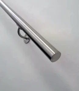
Clearance, gripping-surface profile and bracket projection describe one space, and a nominal rail size tells you almost nothing about that space on its own. A rail specified as a given diameter can sit at a correct nominal size and still leave a hand without room, because what the hand uses is the volume around the rail bounded by the wall on one side and the bracket arms along the run.
The three factors interact in a specific way. The profile sets what the fingers close around, and the ADA Accessibility Standards distinguish circular gripping surfaces, which are checked by diameter within a 1.25 to 2 inch range on covered stairs, from noncircular ones, which require perimeter and cross-section checks instead. Clearance sets how far the gripping surface stands off the adjacent surface, and that guidance calls for at least 1.5 inches of adjacent clearance on covered stairs. Bracket projection sets where that clearance is locally consumed, because the bracket is the only thing between the rail and the wall and it is also the only thing that can reduce the clear space at a support point. The same standards keep the tops and sides of the gripping surface clear and limit obstruction at the bottom to 20 percent of the grip length, which is why bracket attachment position, not just bracket size, controls whether a support is acceptable.
Two drawing practices make this reviewable. Show the clearance dimension measured to the finished wall surface rather than the substrate, since tile, panel and plaster thicknesses are added late and eat the standoff. And show one section at a bracket as well as one between brackets, so the reviewer sees both the open condition and the worst local condition on the same sheet.
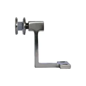
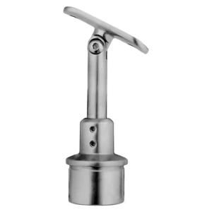
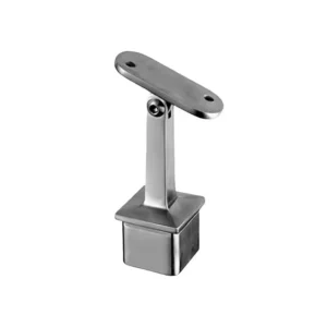
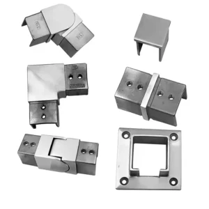
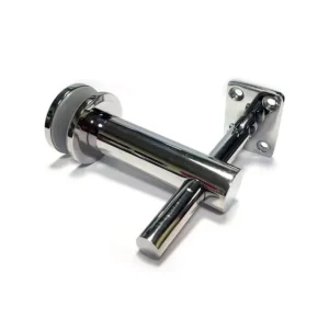
A common specification mistake is approving the rail and the bracket from separate catalog pages. The bracket family determines how far the rail sits off the wall and how the arm meets the tube, so choosing the rail first and the bracket second usually means the clearance was never a decision at all. Top mount handrail brackets change this interface again, because the support reaches the rail from underneath rather than from the side, which keeps the sides of the grip open while placing the obstruction where the bottom-obstruction allowance applies.
Coordinate Extensions and Returns With Circulation and Terminations
| Project interface | Coordination check | Approval outcome |
|---|---|---|
| Landing circulation | Place each extension and return in the landing circulation layout. | Confirm that the termination and the intended circulation are coordinated. |
| Adjacent walls | Check the available wall relationship at each termination. | Confirm that the return detail fits the actual wall condition. |
| Posts | Check how the rail end or return relates to each adjacent post. | Resolve the post interface before approving the termination. |
| Termination detail | Show how every extension ends or returns. | Confirm that each termination is explicit in the project drawings. |
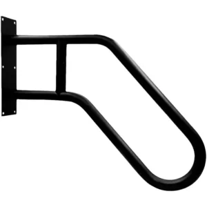
Extensions are the part of the layout where the handrail stops being a stair component and starts competing with the floor plan, so coordinate them against the landing circulation before fixing their length or direction. On covered stairs, the ADA Accessibility Standards call for a top extension that runs horizontally at least 12 inches from the nosing of the first riser, and a bottom extension that continues at the slope of the flight for a horizontal distance of at least one tread depth beyond the nosing of the last riser. Those extensions then return to a wall, guard or landing surface, or continue to the handrail of an adjacent flight. Inside turns and certain hazardous-condition alterations carry their own exceptions, so confirm which applies before shortening anything.
A horizontal extension of that length projects into the landing. Where the landing is also a door approach, a corridor crossing or a space with a required clear width, the extension and the circulation have to be drawn on the same plan. The fix is usually a change in the stair or landing layout rather than a change in the extension, which is why the conflict is cheaper to find on a plan than on site.
The return detail depends on what is actually there at the end of the rail. A return to a wall needs a wall within reach at the right height and a substrate that will take the fixing; on a stair where the wall stops short of the extension, the return has no surface to meet and the detail has to become a return to the landing or a continuation to the adjacent flight. Where a post sits near the rail end, decide whether the rail terminates into the post, passes it or returns before it, because an unresolved post relationship leaves the installer cutting on site.
Every extension needs an explicit termination on the drawing. A rail end drawn as an open line is the single most frequent source of field improvisation on surface mounted stair handrail work, and the improvised version is the one that shows up in the final inspection.
Separate Geometry Review From Base-Plate and Anchor Verification
| Review scope | What it addresses | What it does not establish |
|---|---|---|
| Handrail geometry | Continuity, clearance, gripping-surface profile, bracket projection, extensions, and returns | Base-plate adequacy, anchor adequacy, or the installed load path |
| Project-specific connection review | Base plates, anchors, and the installed load path under the project conditions | Completion of the separate handrail geometry review |
A completed geometry review tells you the handrail layout is dimensionally coordinated; it does not tell you the installed assembly carries load. Keep the two reviews separate on paper so that a signature on the layout is never read as approval of the connection.
The boundary is clean in practice. Geometry covers continuity, clearance, gripping-surface profile, bracket projection, extension lengths and termination details — everything that can be judged from dimensioned drawings and the governing requirements. Connections cover base plates, anchors, substrate capacity, edge distances and the load path from the rail through the bracket into the wall, stringer or slab. Those depend on what the structure actually is, which is project information the layout drawing does not contain.
ASTM E985-24 supports this split. Its scope includes basic design and minimum load and deflection criteria for permanent metal stair and guard systems and handrails, while assigning specific field-condition design criteria to designers, specification writers and code agencies. That is a standard telling you, in its own scope, that the field condition is a separate determination. The abstract also excludes ballasted systems and workplace occupancies governed by occupational-safety railing requirements, so projects in those categories need their own basis.
Because guard and handrail loads are a structural matter, the acceptance of any particular base plate, anchor type, embedment or edge distance belongs to the project’s approved procedure and its designated approver, working from the structural drawings and the substrate information. A supplier can state what a bracket or base is made of and how it mounts; whether that mounting is adequate on a specific wall is decided with the project’s structural information in hand.
Approve the Layout After Jurisdiction, Drawings, and Responsibilities Align
Approve the layout when three conditions hold at once: the governing jurisdiction and the stair’s coverage are confirmed in writing, the drawings show continuity, clearance, profile, bracket projection and every termination at the actual conditions, and the connection review is identified as a separate open item with a named owner. Missing any one of the three turns approval into an assumption that someone else will resolve later.
The alignment check is worth doing as a short reconciliation rather than a second review. Confirm that the dimensions on the drawing came from the document the project named as its basis, not from a generic guide. Confirm that the sections showing clearance were drawn at bracket locations and at finished wall surfaces. Confirm that each flight’s top and bottom extension has a drawn end condition and that the landing plan shows those extensions in the circulation. Confirm that the geometry sheet carries no statement implying the anchors or base plates have been accepted.
Where a surface mounted stair handrail is being quoted or detailed with a supplier, have the following ready before the conversation: the stair plan and sections with riser and tread dimensions and landing layouts, the wall or stringer construction and finish thickness at each mounting line, the specified stainless-steel grade and finish, the exposure condition, and the project document being used as the handrail basis along with any jurisdiction-specific interpretation already issued. With those in hand, bracket selection, rail profile and termination fittings can be resolved in one pass instead of iterating through drawings that each answer a different question.
If any of that information is still open, the one to chase first is the finished wall construction at the mounting line. It governs clearance, bracket projection and the connection review simultaneously, and it is the variable that most often changes after the rail has already been ordered.
Frequently Asked Questions
Q: What should be included in the review package before a surface-mounted stair handrail layout is approved?
A: Include the identified jurisdiction and applicable project requirements, stair plans and sections, each flight and landing condition, the proposed gripping-surface profile, bracket geometry, and all wall, post, extension, and return interfaces. Also state who is responsible for the separate base-plate and anchor review so that geometry approval is not mistaken for connection approval.
Q: Can one typical handrail detail be approved for every stair run in a project?
A: Only where the relevant conditions are genuinely the same. Compare each run for changes in landings, adjacent walls, posts, transitions, brackets, and terminations, and create a specific detail wherever a change could affect the usable gripping path or available clearance.
Q: How should the team handle a conflict between gripping-space geometry and the proposed support arrangement?
A: Treat it as an unresolved interface rather than approving either item in isolation. Show the rail profile, clearance, and bracket projection together at the affected location, then coordinate the geometry change while keeping base-plate, anchor, and load-path verification under the project-specific connection review.
Q: What information should be marked unresolved instead of being assumed during submittal review?
A: Mark the item unresolved when the governing project requirements are not identified, a transition or landing condition is not shown, a termination conflicts with circulation or an adjacent element, or connection responsibility is unclear. Record the exact missing drawing, decision, or responsible party needed before approval can proceed.
Q: When does an approved handrail layout need to be checked again?
A: Recheck the affected locations whenever the rail profile, bracket projection, landing arrangement, adjacent wall or post, extension or return detail, base plate, or anchor concept changes. The follow-up review should cover the interfaces touched by the change and retain the boundary between geometry approval and connection verification.