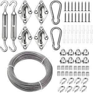
A cable railing tensioner installed at the wrong starting position can look correctly tensioned at handoff and still leave no room to correct sag, re-tension after settling, or release the cable for a repair. The adjustment range available at the moment of fit-up is fixed by decisions made earlier in the installation, not by the tensioner hardware alone, which makes the starting position a judgment call rather than a default setting.
Starting Position and Usable Travel
| Initial tensioner position | Take-up travel | Release travel | Installation decision |
|---|---|---|---|
| Documented position with usable travel in both directions | Preserved for final tensioning | Preserved for release or correction | Use as the starting position after checking the measured run geometry and fitting setup |
| Fully open | Available | No further release reserve | Reposition before tensioning so release travel remains available |
| Fully bottomed | No further take-up reserve | Available | Reposition before tensioning so take-up travel remains available |
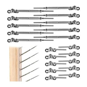
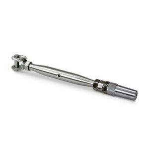
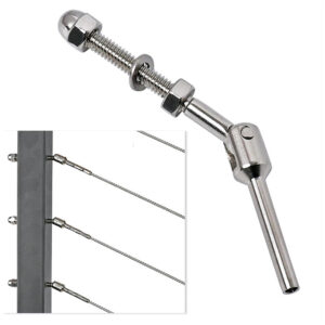
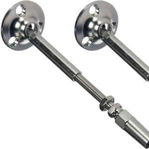
The starting position of a cable tensioner determines whether the installer has room to move in either direction once the run is loaded. A tensioner begins its working life somewhere along a threaded travel path, and that position is not neutral: wherever the thread sits when the cable is first secured sets the ceiling on how far it can still be tightened and the floor on how far it can still be loosened. Where the tensioner is set fully open at the start, the installer gains maximum take-up capacity but gives up any ability to release tension later if the run needs slackening for adjustment or component replacement. Where it is set fully bottomed, the reverse is true: release capacity is available, but there is no remaining thread to take up slack discovered during final tensioning.
This matters because cable railing installation is rarely a single-pass operation. Initial tensioning, inspection, seasonal movement, and occasional re-tensioning after a run settles all draw on the same finite travel. A documented starting position — one established from the measured run rather than chosen by habit or convenience — preserves usable travel in both directions, so the installer is not forced to choose between under-tensioning the run or discarding the ability to correct it later.
The condition that changes this judgment is how much is already known about the run at the time the tensioner is set. Where the post spacing, cable length, and terminal hardware have been measured and confirmed before the tensioner is placed, the installer can position it near the center of its travel with confidence that both directions remain available. Where those inputs are still uncertain — a run that has not been field-measured, or a terminal whose insertion depth has not been finalized — starting at either extreme becomes a way of deferring a decision rather than making one, and it transfers the risk of a travel-limited fitting downstream to whoever performs final tensioning or later service. Adjustable cable tensioners are selected specifically because they offer this working range, and that range only functions as intended when the starting position is chosen with the full run geometry in view rather than set before the geometry is confirmed.
Cable Length Terminal Insertion and Geometry
| Fit-up input | Project-specific value to establish | Decision use |
|---|---|---|
| Cable cut length | Cut length for the measured run | Determine how much tensioner adjustment is consumed during initial fit-up |
| Terminal insertion depth | Installed insertion depth | Include the terminal position when assessing adjustment already consumed |
| Post-to-post geometry | Measured geometry of the cable run | Set the length basis for the initial tensioner position |
| Opposing end fitting | Installed fitting and its position | Account for the opposite end when checking the remaining tensioner range |
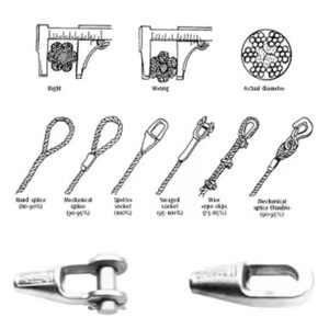
The tensioner’s remaining range at the point tension is applied is not a property of the tensioner body alone; it is the result of several fit-up inputs acting together. Cable cut length sets the raw material available for the run, but the cut length is not the same as the usable length once terminal hardware is accounted for. Terminal insertion depth — how far the cable sits inside the end fitting once swaged, formed, or otherwise secured — consumes part of that cut length before any tensioning begins, and a deeper insertion than planned shortens the effective cable and shifts the burden of closing the remaining gap onto the tensioner.
Post-to-post geometry adds another variable. A run measured and cut for one post spacing will not transfer directly to a different spacing without adjusting either the cable length or the amount of tensioner travel called on to close the distance. Where posts are set slightly out of the designed spacing, or where a post face is not perfectly perpendicular to the cable line, the geometry the tensioner must accommodate changes even though the cable and terminal remain the same.
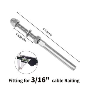
The opposing end fitting completes the picture. A tensioner at one end does not operate in isolation; it is closing the distance between its own body and whatever is fixed or adjustable at the far end of the run. Where the opposing fitting is also adjustable, some of the needed correction can be distributed between the two ends. Where the opposing end is fixed, the full burden of closing any gap between measured geometry and actual geometry falls on the single tensioner, which consumes more of its travel before tension is even applied. Threaded cable end fittings installed at the non-adjustable end should be checked for their installed position before the tensioner side is set, since their position is part of what determines how much range remains.
Taken together, these four inputs establish how much of the tensioner’s total travel is already spent before the installer begins deliberate tensioning. None of them can be read from the tensioner itself after installation; they must be established from the run as built.
Thread Engagement Marks for Inspection
| Inspection check | What to compare | What the observation establishes |
|---|---|---|
| Initial thread position | Initial engagement mark against the documented starting position | Provides the baseline for later adjustment checks |
| Final thread position | Final position against the initial mark | Shows how much adjustment was used during tensioning |
| Thread engagement | Current position against the engagement mark | Makes incomplete engagement visible for correction |
| Tensioner body position | Current body position against the available travel | Makes exhausted travel visible and triggers a fit-up check |
Because the inputs that consume tensioner travel are not visible once the assembly is closed up, a documented mark at the point of initial thread engagement gives inspection something concrete to compare against later. Marking the initial position before any tensioning begins establishes a baseline specific to that fitting on that run, rather than relying on a general expectation of what a correctly set tensioner should look like.
Marking the final position after tensioning is complete turns that baseline into a record of how much adjustment the run actually required. Where the distance between the initial and final marks is small, the fit-up inputs were close to what was planned. Where the distance is large, more of the available range was consumed than expected, which is itself information about the run — not simply a note that tensioning was completed.
The value of these marks extends past the initial installation. At any later inspection, comparing the current thread position against the engagement mark shows whether engagement remains adequate or has become marginal, which is a different question from whether the cable currently reads as tensioned. A cable can feel correctly tensioned to the hand while the thread engagement behind that tension has become minimal, and only a mark-based comparison exposes that condition before it becomes a failure to inspect rather than a condition to correct.
Comparing the current body position against the known travel limits serves a related but distinct purpose: it shows whether the tensioner has reached the end of its available range, independent of whether the current tension feels adequate. A tensioner can be at the end of its travel and still be holding acceptable tension at the moment of inspection, which is exactly the condition that marks are meant to catch before it becomes a problem discovered only when further adjustment is needed and none remains.
Adjustment Reserve for Final Tensioning
Reserving part of the tensioner’s travel for final tensioning is a different decision from choosing a starting position, though the two are related. The starting position sets the total travel available; the reserve decision determines how much of that travel is deliberately left unused at each stage so that a later, named step in the assembly instructions has range to work with.
This distinction matters because the point at which “final” tensioning occurs is defined by the assembly sequence, not by when the installer judges the cable to feel tight. Where the manufacturer’s assembly instructions call for an initial set, a settling period, and then a final tensioning pass, reserve must be sized to survive the intermediate step and still leave range for the step the instructions identify as final. Treating an early stage as final — because the cable already reads as tensioned — consumes reserve that the documented sequence assumed would still be available.
The same reasoning applies to reserve intended for service rather than initial installation. A cable run that is correctly tensioned at handoff may still need adjustment after the structure settles, after a seasonal temperature swing shifts the cable’s effective length, or after a terminal fitting is replaced. Reserve left for this purpose is only usable if the starting position and the fit-up inputs covered earlier did not already consume it during initial installation. Where a project anticipates this kind of service access, the amount of reserve required should be confirmed against the named assembly instructions for that specific tensioner, since different tensioner designs allocate travel differently and a reserve appropriate to one product’s working range is not automatically appropriate to another’s. Reserve sized this way is a property of following the documented sequence, not a substitute for it: tightening further on a travel-limited fitting does not create reserve where the underlying cable length or frame geometry is the actual constraint.
Exhausted Travel as a Fit-Up Warning
A tensioner that reaches the end of its travel before the run achieves acceptable tension is reporting a condition in the fit-up, not a defect in the tensioner. The tensioner’s range was sized for a defined amount of correction; where the actual gap between the as-built geometry and the designed geometry exceeds that range, the hardware runs out of adjustment before the installation is complete. Reading this as a hardware problem and responding by forcing further tightening or substituting a different tensioner in the same position treats the symptom as the cause.
The corrective response belongs upstream, at the inputs established earlier: cable cut length, terminal insertion depth, post-to-post geometry, and the opposing end fitting. Where exhausted travel appears, the run should be checked against those same inputs to identify which one consumed more of the available range than the design anticipated — a cable cut short, a terminal inserted deeper than planned, posts set out of spec, or an opposing fitting positioned differently than expected. Correcting the identified input restores the tensioner’s intended working range; correcting it by over-torquing the tensioner body does not, and it transfers an unresolved geometry problem into the hardware instead of out of the assembly.
This is also where the marks described earlier serve their clearest purpose: a tensioner found at or near the end of its travel, with its body position matched against the documented engagement marks, gives the inspector a specific point to begin tracing back through the fit-up record rather than a general impression that something is wrong. Cable tensioner systems sized and selected for a given run assume that the fit-up inputs fall within an expected range; where field conditions move outside that range, the named assembly instructions and the project’s own measured geometry — not the tensioner’s remaining thread — are the correct place to resolve the discrepancy before the run is accepted as complete.
Frequently Asked Questions
Q: Is it acceptable to start with the cable tensioner fully open or fully bottomed?
A: No. Set and document an initial position that preserves usable travel for both take-up and release after checking the measured run geometry and fitting setup.
Q: What information should be established before setting the initial tensioner position?
A: Establish the cable cut length, terminal insertion depth, post-to-post geometry, and the type and position of the opposing end fitting. Assessing these together shows how much adjustment the assembled run will consume before tension is applied.
Q: What should the installer do if the tensioner reaches the end of its travel before the cable is properly tensioned?
A: Treat exhausted travel as a fit-up warning and recheck the cable length, frame geometry, terminal insertion, and opposing fitting position. Further tightening of a travel-limited fitting does not correct an underlying length or geometry problem.
Q: How much adjustment should be reserved for final tensioning and later service?
A: Keep usable adjustment available in the directions required by the named assembly instructions rather than assuming a universal amount. Record the initial and final thread positions so the project team can see how much travel was used and what remains.
Q: Do ISO 2408 or ASTM E985 specify the required adjustment range for the tensioner?
A: No. ISO 2408 addresses steel wire ropes within its stated scope, while ASTM E985 provides basic railing design and load or deflection criteria; neither sets tensioner travel or terminal capacity. Confirm the fitting range from the applicable assembly instructions and resolve project geometry and acceptance requirements with the responsible designer and jurisdiction.