Fixing the tensioner type before the end post conditions are confirmed is one of the most common sources of rework in cable railing projects. A stud end threaded too deep into a post can exhaust its entire adjustment range before the cable reaches stable tension — leaving no corrective path short of pulling the fitting and starting over. That single omission becomes a scheduling problem when it occurs mid-installation across multiple runs. The decision that prevents it is straightforward: freeze tensioner type only after the shop drawing confirms available travel, finished projection, tool clearance, and post geometry simultaneously.
Adjustment Mechanisms Behind the Main Tensioner Types
The core mechanical difference between turnbuckles, stud ends, and adjustable terminals is not appearance — it is how and where adjustment is applied, and how much corrective range the fitting can absorb once installation is underway.
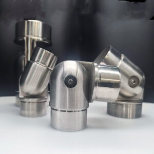
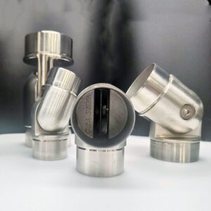
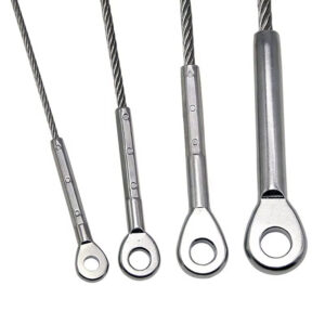
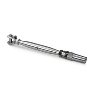
A standard turnbuckle extends and retracts through opposing threaded shafts, which means both ends of the body are consuming or releasing thread simultaneously. The adjustable closed-body variant adds rotational positioning — it can be oriented across a 0–180 degree range before locking, which is a useful design input for non-linear cable runs where a fixed turnbuckle body axis would conflict with post geometry or intermediate hardware. This is not a performance specification; it is a layout tolerance that becomes relevant when the run changes direction or angle.
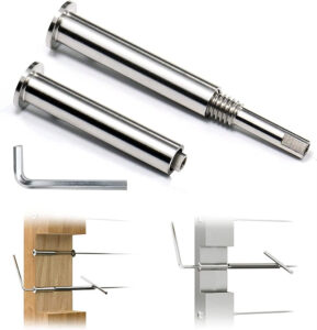
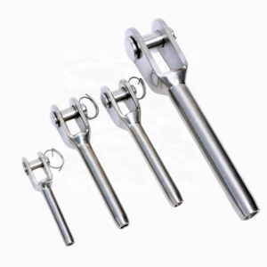
Threaded ratchet stud ends use a different mechanism: tension builds by rotating the stud — typically with a 3/16″ Allen wrench — until the cable reaches a target resistance. The ~225 lbs target commonly cited for this fitting type is a process implementation figure, not a code-mandated threshold, and it should be treated as a calibration reference rather than a compliance value. What matters practically is that the stud has a finite thread travel, and if the fitting is installed with the stud already near its end of travel — often the result of deep insertion into a post or of pre-threading past the intended starting position — the wrench can run out of purchase before the cable reaches stable tension.
The planning implication for long or high-tension runs is to specify tensioner fittings on both ends of the run rather than anchoring one end with a fixed terminal. Doubling the adjustment source doubles the corrective range available during tensioning, which prevents the scenario where a single fitting must absorb all the slack and thermal movement in a long cable span. This is a planning criterion that should appear in the shop drawing before hardware is ordered, not an adjustment made during installation. Esang’s adjustable cable tensioners are designed to support this dual-end configuration where run length or geometric complexity warrants it.
Space and Tool Access at the End Post
Tensioner selection cannot be made independently of end post geometry. The fitting has to fit inside, through, or beside the post — and it has to leave enough clearance for whatever tool is used to apply or confirm tension.
A concealed terminal designed to sit entirely inside the post — typically around 2″ in overall length — can be installed into a 2×2 or larger metal post without any external projection. That is a useful design figure because it sets the minimum post section for concealed termination. If the post is smaller or the wall thickness is such that the fitting cannot be inserted square, the concealed approach fails before installation begins. The fitting length must be confirmed against the post’s interior dimension before the terminal type is committed.
Swageless fittings reduce the tool burden significantly — installation with pliers and an Allen key eliminates the need for a crimping press on site. That trade-off matters for projects where a swaging machine is not available or where site conditions limit what can be brought to the work area. It is worth noting, however, that swageless fittings are not appropriate for every cable diameter or load scenario, and tool simplicity should not be the primary selection criterion where cable construction or tension requirements are driving the specification.
Corner posts introduce a collision risk that is often overlooked in layout: when two cable runs terminate inside the same post from perpendicular directions, the hardware from one run can physically block the fitting for the other if both are at the same elevation. Offsetting cable heights by approximately 1/2″ between intersecting runs at a corner post is a planning input that prevents this interference — but it has to be shown on the shop drawing, because a 1/2″ offset introduced during installation without prior coordination can shift the visible cable line relative to adjacent panel runs and create an alignment discrepancy that reads as an installation error.
Visible Hardware Versus Concealed Terminations
The decision between exposed and concealed terminations is often treated as an aesthetic choice, which is accurate as far as it goes. The downstream consequence that is less often considered is service access — and it becomes a real constraint in commercial projects where re-tensioning or cable replacement may be required after the railing is commissioned.
Exposed hardware, including visible turnbuckles and external stud ends, is easier to inspect and easier to service. An installer or maintenance technician can identify whether a fitting has moved, whether thread engagement is still adequate, and whether adjustment is needed, without disassembling the post or removing covers. That accessibility has a cost in appearance — the hardware is visible from multiple angles — but it represents a maintenance advantage, particularly in installations where the cable will be subject to high traffic loading or significant thermal cycling.
Concealed terminals improve the finished appearance considerably and are appropriate where the visual specification requires clean, hardware-free end posts. The trade-off is that re-tensioning requires access to the interior of the post, which may involve removing a cap, inserting a tool through a limited-diameter access point, or in some cases partially deconstructing the termination. If replacement becomes necessary — because a cable has been damaged or needs to be upgraded — extracting a concealed fitting from a post that was not designed for field disassembly introduces significant labor relative to removing a visible external fitting.
Where runs terminate at each level change rather than continuing across multiple levels, the hardware count at transitions increases visibly. A modular approach that terminates at each level introduces fittings at every transition point; a continuous run conceals those intermediate hardware points but transfers its own complications, particularly on multi-level configurations. Neither approach is inherently superior; the relevant question is whether the visible hardware at transitions or the service constraints of concealed terminations creates more exposure for the specific project and its long-term maintenance plan. For further background on how these trade-offs apply across different project types, the Complete Stainless Steel Cable Railing Guide covers installation and specification considerations in more depth.
Scheduling Risks Across Mixed Cable Runs
The tension behavior of a cable run is not isolated to the tensioner — it is affected by every post transition, every direction change, and every dissimilar fitting the run encounters. These factors compound when the tensioner type is not consistent across a project.
Continuous cable runs routed across three levels without independent terminations at each level change can lose up to 40% of effective tension to friction at post transitions. That figure is a failure risk pattern, not a guaranteed test result, but it describes a real mechanism: tension applied at one end has to overcome friction at every post eyelet or through-post transition before it reaches the far end of the run, and on multi-level geometry that friction accumulation is significant. The result is a cable that reads as tensioned at the fitting end but sags visibly mid-run or at the far level — a condition that only becomes apparent after commissioning, when pulling the fitting back apart is already a disruptive correction.
The modular alternative — terminating runs independently at each level change — allows each segment to be tensioned to its own target without that tension being reduced or distributed unevenly by post friction at transitions. It adds hardware count and may introduce visible fittings at intermediate posts, but it gives the installer and the inspection team a consistent, independently verifiable tension state at each segment.
Mixing tensioner types across a project introduces a different class of risk: inconsistent take-up, different tool requirements at each fitting type, and non-interchangeable replacement stock. A project with turnbuckles on some runs and stud ends on others will require separate field tool kits and separate spare parts inventory. When a fitting needs to be replaced — whether during construction or later maintenance — the technician has to identify which type is present, confirm they have the right replacement on hand, and apply a different adjustment procedure than they used on the previous run.
| Risk Factor | Consequence | What to Clarify |
|---|---|---|
| Continuous runs across multiple levels | Up to 40% effective tension loss from friction, leading to uneven tension and sagging | Clarify whether runs will be terminated at each level (modular approach) to allow independent tensioning and prevent imbalance |
| Mixing tensioner types on a single run | Inconsistent take-up and risk of exhausting adjustment travel before reaching stable tension | Confirm that identical tensioner fittings are specified on both ends to ensure symmetrical adjustment |
Using identical tensioner fittings on both ends of a run — and using the same fitting type consistently across runs — prevents these stocking and procedural inconsistencies from accumulating into an ongoing maintenance burden.
Shop Drawing Evidence Required for Approval
The shop drawing is where tensioner selection stops being a product decision and becomes a coordination document. Submittals that specify a tensioner type by name but omit the dimensional and tool access data that the type depends on are difficult to approve because the reviewer cannot verify that the hardware will function as described in the actual post geometry.
The minimum evidence that supports a defensible submittal is the fitting length — because without it, no one can confirm that the terminal fits inside the post — alongside an explicit statement of post type and size compatibility. A 2″ concealed fitting works in a 2×2 metal post; it may not work in a smaller section or in a wood post where interior dimensions differ from nominal. The drawing has to make that relationship visible, not leave it as an assumption.
Tool identification matters for a related but separate reason: if the field adjustment requires a 3/16″ Allen wrench, that wrench needs to reach the fitting in the as-installed condition. On a concealed terminal, the wrench access point may be a small hole in the post cap or side face — and if the drawing does not show that access dimension, no one can confirm during review that tensioning is physically possible after the post is assembled. The same logic applies to the tension target: a documented ~225 lbs reference gives the installer and the inspector a field-verifiable figure. Without it, tension is applied to feel, and variation between installers or visits produces inconsistent results that are hard to defend if the installation is later disputed.
| Required Evidence | Example / Specification | Why It Matters |
|---|---|---|
| Fitting length | e.g., 2″ for concealed terminal | Ensures fitting fits inside the post and confirms termination strategy |
| Post type and size compatibility | Must be stated on drawing | Verifies that hardware can be physically installed in the intended post |
| Tension tool identification | e.g., 3/16″ Allen wrench | Confirms that the correct field-adjustment tool will be available |
| Target tension setting | ~225 lbs | Validates that the hardware can achieve and hold the specified tension |
| Post size compatibility | e.g., 2×2 or larger metal post | Prevents field conflicts where a fitting cannot be inserted or adjusted inside the post |
Drawings that omit any of these inputs put the approval decision in the reviewer’s hands without giving the reviewer enough to go on — which typically results in a revision request that delays material release. The practical effect is that the shop drawing review cycle becomes a scheduling constraint rather than a coordination step.
The central judgment in tensioner selection is not which fitting looks best or which is cheapest per unit — it is whether the fitting’s adjustment range, physical length, and tool clearance are compatible with the end post as designed before the hardware is ordered. A fitting that exhausts its travel before the cable reaches stable tension leaves no corrective path that does not involve pulling the termination and starting over, which is a labor cost and schedule impact that procurement rarely anticipates.
Before committing a tensioner type, confirm fitting length against post interior dimensions, identify the access point for the adjustment tool in the as-assembled condition, verify whether the run requires single or dual-end tensioning given its span and geometry, and check whether corner post configurations require a height offset to prevent hardware collision. Those four checks, all of which should be visible on a complete shop drawing, determine whether the tensioner type selected in the specification will actually function as intended in the field.
Frequently Asked Questions
Q: What happens if the post material is wood rather than metal — do concealed tensioner lengths still apply the same way?
A: No, wood posts change the calculation significantly. A 2″ concealed fitting that fits cleanly inside a 2×2 metal post may not have a reliable interior dimension to seat against in a wood post, where nominal sizing, grain direction, and bore tolerances differ. Before specifying a concealed terminal in wood construction, confirm the actual drilled interior dimension against the fitting’s body length and verify that the post wall has enough material remaining after boring to hold the load without splitting.
Q: After the shop drawing is approved and hardware is ordered, what is the first on-site check before tensioning begins?
A: Verify that the adjustment tool can physically reach the fitting in the fully assembled condition before a single cable is tensioned. If the access point — a cap hole, side port, or open post end — is obstructed by adjacent structure or a cover installed during framing, no amount of correct hardware selection recovers the situation without disassembly. Confirming tool access in the as-built condition, not the drawing condition, is the first practical gate before tensioning work starts.
Q: At what run length or configuration does using a tensioner on only one end become genuinely inadequate rather than just less ideal?
A: Single-end tensioning becomes a real risk rather than a marginal trade-off once friction at post transitions is a factor — specifically on runs crossing multiple level changes, where up to 40% of applied tension can be lost before reaching the far end. At that point, a single fitting must absorb not only the cable’s natural slack but also the friction deficit, which can exhaust its travel range before stable tension is reached mid-run. Dual-end tensioning should be the default specification on any run with more than one level transition, not an upgrade applied after a problem appears.
Q: Is a turnbuckle or a stud-end tensioner easier to re-tension after the railing has been in service for a year or more?
A: A turnbuckle is generally easier to re-tension in service because the adjustment is applied externally with a wrench on the body, without requiring access to a concealed interior or a specific port alignment. A stud end requires inserting an Allen wrench into the fitting, which is straightforward if the post end is open but becomes a constraint if the access point has been covered or if the fitting has corroded slightly at the thread. For projects where annual re-tensioning or inspection is expected — high-traffic commercial installations or coastal environments with significant thermal cycling — the accessibility advantage of an external turnbuckle carries more long-term weight than it does on a low-maintenance residential run.
Q: Does specifying Esang heavy-duty turnbuckles versus standard turnbuckles change which shop drawing dimensions need to be documented?
A: Yes, because heavy-duty turnbuckles typically have greater body length and jaw or eye dimensions than standard fittings, which directly affects whether the fitting clears adjacent hardware at the post and whether the projection beyond the post face meets the finished appearance requirement. The same four drawing checks apply — fitting length against post interior, tool access point, run geometry for single or dual-end configuration, and corner post height offset — but the actual figures change. Substituting a heavy-duty fitting after a standard fitting was submitted without revising the dimensional drawings creates a gap between what was approved and what is installed, which is a common source of revision requests during inspection.