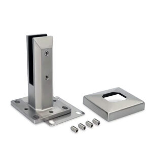
When glass in an adjustable base shoe reads as straight along the top rail but the joints tighten or open irregularly from panel to panel, the installer is left asking which problem the shoe’s adjustment was meant to solve and which one it just concealed. That question has to be settled before adjustment begins, not inferred afterward from how the finished run looks.
Establish a Control Datum and Map Channel Deviations
| Survey item | Record before glass placement | How it guides alignment |
|---|---|---|
| Control datum | The control datum used for the run | Provides one reference for channel and glass alignment |
| Channel deviation | Channel deviation relative to the control datum | Separates an existing channel or substrate error from adjustment available within the named shoe’s limits |
Alignment work on an adjustable glass base shoe only has meaning relative to a fixed reference. Without a control datum established before any glass is set, there is no way to tell whether a gap, a lean, or an inconsistent reveal comes from the channel or supporting substrate, or whether it is something the shoe’s own adjustment range is meant to correct. The datum is not a preference; it is the one line against which every later measurement on the run is compared.
Channel deviation is a separate fact from adjustment capacity, and treating them as the same thing invites trouble. A channel that runs slightly out of line with the datum has a fixed, physical cause: a substrate tolerance, an anchor position, a prior construction sequence. The adjustable shoe’s range, by contrast, is a designed allowance for bringing glass into line within defined limits. Where the recorded channel deviation falls inside the shoe’s documented adjustment range, the installer has latitude to correct at the glass. Where it exceeds that range, the deviation is a substrate or channel condition that adjustment hardware cannot resolve, no matter how it is manipulated.
This distinction changes the sequence of decisions on site. If channel deviation is mapped first and compared to the datum, the installer knows in advance which panels will need adjustment near the edge of the shoe’s range and which will need none. Skipping this step and discovering the deviation only once glass is loaded removes that planning advantage; by then, adjustment decisions are being made under the pressure of panels already in place, with less room to distribute correction evenly across the run.
The practical value of this mapping is that it keeps the adjustment conversation honest. An installer who can point to a recorded deviation against a known datum can distinguish, to a supplier or a design team, between a hardware question and a substrate question. Without that record, every irregularity in the finished run looks like a hardware issue, even when the shoe performed exactly as intended within its range. Esang’s glass base shoe channels are specified and supplied against the dimensional and anchor information a project provides, which is why the deviation-to-datum record matters before ordering or adjustment decisions are finalized, not only during installation.
Confirm Glass Build-Up, Wedges, Gaskets, and Adjustment Hardware as One System
An adjustable base shoe does not function as a single part; it functions as an assembly of glass thickness, setting blocks or wedges, gaskets, and the adjustment hardware itself, all calibrated to work together inside one channel geometry. Changing any one element without confirming the others changes how the whole system behaves, even when the shoe body and the glass both look correct in isolation.
Glass build-up is the dimension that ties the rest of the system together. A given shoe configuration is designed around a defined build-up tolerance, meaning the wedges and gaskets around the glass are sized to take up the remaining space within the channel. Where the glass build-up shifts, because of interlayer thickness, edge treatment, or an edge condition different from what the shoe configuration assumes, the wedges and gaskets that previously filled the channel correctly may no longer seat the same way. The result can be a glass pane that is visibly in the channel but not supported the way the adjustment hardware assumes it is.
This is why approval has to apply to the assembly, not to the glass or the hardware separately. A gasket substituted for a different profile, or a wedge sized for a different build-up, can still physically fit into the channel while changing the pressure distribution, the drainage path, or the amount of adjustment range actually available at the hardware. A shoe’s adjustment limits are established for its approved configuration; introducing an unapproved wedge, gasket, or build-up combination means the adjustment hardware is now operating under conditions it was not configured for, even if nothing about the installation looks unusual from the top rail.
The practical implication for sourcing and specification is that build-up, wedge, gasket, and hardware should be confirmed as one package before glass is set, not reconciled individually as each component arrives. Where a project changes glass type, interlayer, or edge condition partway through specification, that change needs to be checked against the shoe configuration’s approved build-up range before assuming the existing wedges and gaskets still apply.
Sequence Panels to Protect Joint Spacing and the Finished Top Line
The order in which panels are set and adjusted in a glass base shoe run determines whether small corrections stay distributed evenly or accumulate into a visible problem at one end of the run. Each panel’s position interacts with its neighbors through the joint between them; adjusting one pane’s lean or height without accounting for that interaction shifts the burden of correction onto the next joint rather than resolving it.
Where a panel is adjusted in isolation to bring it into line with the control datum, the joint on either side of it absorbs whatever change was made. If the adjacent panel was already set, the joint spacing between the two may close or open beyond what the detailing allows, even though each pane individually now reads as correctly aligned. This is the mechanism behind a run that looks straight pane by pane but shows irregular reveals or a wandering top line once several panels are in place.
Sequencing to protect joint spacing means treating each adjustment as a decision that affects at least two panels, not one. The panel being corrected and the panel it will be checked against both need to be evaluated for the resulting joint width and edge condition before the adjustment is locked. Where the top line is the controlling reference for the run, as it often is in a continuous glass balustrade, panel-by-panel correction toward the datum has to be checked continuously against the top line, not only against the immediately adjacent panel, since a series of individually small corrections can still produce a cumulative drift across a longer run.
This is also where the trade-off between correcting early and correcting late becomes concrete: where a deviation is caught and distributed across several unset panels still ahead in the sequence, the correction can be shared in small increments that preserve both joint spacing and the top line; where the same deviation is only discovered after most of the run is already set, the remaining adjustment has to be concentrated in fewer panels, which increases the visible change in joint width at those locations. Neither condition is a hardware failure; both are a consequence of when, in the sequence, the deviation was identified.
Correct Alignment Within the Named Shoe’s Adjustment Limits
| Condition being assessed | Alignment decision | Boundary to retain |
|---|---|---|
| Recorded channel or substrate deviation | Treat it as an existing condition against the control datum before using shoe adjustment | Do not use adjustment to hide a substrate error |
| Glass alignment correction | Use the named shoe’s adjustment only within the system’s permitted range | Confirm the permitted range for the named shoe configuration |
| Effect on the next panel | Accept the correction only if the sequence still preserves joint spacing, the top line, and edge conditions | Do not correct one pane at the expense of the next |
The decision at the center of this work is whether a proposed correction belongs to the glass or to the channel, and whether the named shoe’s adjustment range is the right tool for the deviation in front of the installer. This decision has to be made panel by panel, because the same visual symptom, a pane that leans or sits proud of its neighbors, can have either cause.
Where the recorded channel or substrate deviation, established against the control datum, already accounts for the misalignment, the correct response is to treat that deviation as an existing condition to be resolved at the channel or substrate, not absorbed into the glass adjustment. Using the shoe’s adjustment hardware to compensate for a substrate error moves the hardware toward or past the edge of its permitted range for a reason unrelated to the glass itself, which can leave less range available if a later, unrelated correction is needed on that same panel.
Where the deviation falls within what the named shoe configuration is designed to adjust, the correction should be made at the glass, using the adjustment hardware for its intended purpose, and checked against the permitted range for that specific shoe configuration rather than assumed from a similar-looking product. Adjustment ranges are tied to the shoe’s designed geometry; applying a correction and simply confirming that the hardware physically moved is not the same as confirming the movement stayed within the configuration’s documented limits.
The third test is the one most easily skipped under time pressure: whether the correction, once made, still leaves the sequence able to preserve joint spacing, the top line, and edge conditions for the panels that follow. A correction that satisfies the first two tests, respecting the datum and staying within the shoe’s range, can still fail this third test if it pushes the next joint outside an acceptable width. Where this happens, the choice is not to force the next panel to compensate but to revisit whether the correction should be redistributed earlier in the sequence, which is why panel order and adjustment decisions cannot be evaluated separately from one another.
Lock Off Retaining Components Without Compromising Covers or Drainage
Reaching correct alignment is not the end of the installation sequence; the retaining components that hold the glass in its adjusted position have to be locked off in a way that does not undo the condition that was just set, and that does not interfere with the shoe’s covers or its drainage path. Each of these three elements, retaining components, covers, and drainage, can be affected by the act of locking off, even when the glass alignment itself is undisturbed.
Retaining components are what convert a correctly positioned pane into a fixed one. Where the lock-off procedure for a given shoe configuration applies uneven pressure, or is tightened in a sequence that was not designed into that configuration, the glass can shift slightly from its adjusted position even though the adjustment hardware itself was set correctly beforehand. This is a separate failure mode from the adjustment step and needs to be checked separately, because a pane that was correctly aligned before lock-off is not guaranteed to remain so afterward without verification.
Covers serve a role beyond appearance: they close the channel against the environment and, in many base shoe configurations, work together with the drainage path rather than independently of it. Where a cover is refitted after adjustment without confirming it still seats correctly against the now-adjusted glass position, it can leave a gap that affects weather performance, or it can bind against the glass in a way that applies unintended pressure to the pane. Either condition can be present without being visible from a normal viewing angle.
Drainage is the element most likely to be overlooked once alignment and lock-off appear complete, because a blocked or redirected drainage path produces no immediate visual symptom at the time of installation. Adjustment hardware, wedges, and retaining components all occupy space within the same channel that the drainage path uses; a configuration that worked correctly before adjustment can have its drainage route altered by the adjustment itself, particularly where wedges or shims were introduced or repositioned during the alignment process. Confirming drainage after lock-off, rather than assuming it was unaffected by work done elsewhere in the channel, is part of completing the installation rather than a separate maintenance step.
Verify the Completed Run Against Survey Records and Edge Conditions
| Verification point | Evidence to check | What the check establishes |
|---|---|---|
| Survey baseline | Completed glass run against the control datum and recorded channel deviations | Whether final alignment is consistent with the recorded starting conditions |
| Joint spacing | Joint spacing through the panel sequence | Whether alignment was preserved from panel to panel |
| Finished top line | Top-line alignment across the run | Whether a local correction disrupted the overall line |
| Edge conditions | Glass edge conditions through the run | Whether panel sequencing preserved the intended edge conditions |
| Retaining components | Final lock-off state | Whether retaining components were verified after alignment |
| Covers | Cover condition after lock-off | Whether the covers were verified as part of completion |
| Drainage route | Drainage route after retaining components and covers are in place | Whether the drainage route remains verified |
| Visual straightness | The apparent straightness of the run | Visual straightness alone does not establish that the assembly is complete |
A completed glass run that appears straight does not, by itself, establish that the installation is finished. Visual straightness is a property of the top line as seen from a distance; it does not confirm that the retaining components are locked correctly, that the drainage path is clear, or that the panel-to-panel relationships established during sequencing were preserved through to the last pane set. Treating a visually acceptable run as proof of completion skips the verification step that distinguishes an aligned installation from a finished one.
The first verification returns to where the work started: the completed run has to be checked against the control datum and the channel deviations recorded before glass placement began. This comparison answers a different question than the visual check does. It confirms whether the alignment achieved through adjustment is consistent with the conditions that were documented at the outset, rather than relying on the installer’s memory of what was corrected and where.
The second and third verifications follow the panel sequence through the run rather than treating it as a single finished object. Joint spacing has to be checked across the full sequence, not only at the panels where a correction was known to have been made, because an adjustment at one panel can have affected a joint at a different point in the run. The top line gets the same treatment: a local correction that solved a problem at one panel needs to be confirmed as not having introduced a new deviation elsewhere in the line.
Edge conditions deserve a similar check, since panel sequencing decisions made to protect joint spacing can shift how glass edges sit within their wedges and gaskets, particularly at panels adjusted near the limit of the shoe’s range.
The remaining verifications address what was locked off rather than what was aligned: the final state of the retaining components, the fit of the covers once reinstalled, and the condition of the drainage route once both retaining components and covers are in place. Where any of these checks has not been performed, a straight-looking run does not substitute for the evidence that the assembly behind it is complete. Supporting documentation, such as the base shoe specification questions addressed under channel, anchor, and drainage considerations, is the kind of project record this verification step should be checked against, alongside references such as NGA’s FB33-11 guidance on laminated glass in glass railing systems and ASTM E2358’s scope for glazing performance in permanent railing systems, each applied within its own stated jurisdiction and verified against current project requirements rather than treated as a substitute for project-specific confirmation.
Frequently Asked Questions
Q: How do I decide whether an alignment issue should be corrected through the base shoe or addressed as a channel or substrate issue?
A: Compare the issue with the control datum and the channel deviations recorded before glass placement. Use the named shoe’s adjustment only within its confirmed permitted range; if the proposed correction would hide an existing channel or substrate error, resolve that condition rather than consuming the shoe adjustment.
Q: What information should be confirmed before the first glass panel is placed?
A: Confirm the control datum, recorded channel deviations, glass build-up, named shoe configuration, permitted adjustment range, and approved wedges, gaskets, and adjustment hardware. Also define the panel sequence and the joint-spacing, top-line, and edge conditions that must remain consistent through the run.
Q: Can wedges, gaskets, or adjustment hardware be mixed between different base shoe configurations?
A: Do not assume they are interchangeable. Verify that the glass build-up and each adjustment, wedging, and gasket component belongs to, or is approved for, the same named shoe configuration before using them together.
Q: How can panel alignment be corrected without creating a problem farther along the run?
A: Evaluate each correction against the control datum and its effect on the next panel. Keep the sequence only when joint spacing, the finished top line, and glass edge conditions remain consistent instead of improving one pane at the expense of the next.
Q: Is a visually straight glass run ready for completion sign-off?
A: No. Compare the completed run with the survey baseline, then verify joint spacing, top-line alignment, edge conditions, retaining-component lock-off, cover condition, and the drainage route; visual straightness alone does not establish that the assembly is complete.
Q: Does correct alignment by itself show that the railing meets project performance or compliance requirements?
A: No. Alignment is one installation check, while glass selection, glazing-system design, performance requirements, jurisdictional rules, and project acceptance criteria require separate confirmation against the current project documents and applicable standards.