For marine engineers, naval architects, and vessel operators, specifying stainless steel hardware is a foundational decision for corrosion resistance. Yet, its premature failure in seawater installations is often not a material defect but a predictable electrochemical outcome. The core challenge lies in managing the hidden circuit created when stainless steel contacts other metals in a conductive electrolyte, a process that can rapidly compromise structural integrity. Professionals must move beyond material specification alone to a systems-based understanding of marine electrochemistry.
Attention to integrated corrosion prevention is critical now, as operational demands increase and environmental regulations tighten on coating systems. The longevity of a cleat, through-hull, or shaft depends not just on the stainless grade but on the electrochemical strategy governing its entire installation. This requires a shift from viewing hardware as isolated components to treating them as parts of a controlled electrochemical system, where design, material pairing, and maintenance are inseparable.
The Galvanic Corrosion Mechanism Explained
The Electrochemical Battery in Seawater
Galvanic corrosion is an electrochemical degradation process, not a chemical reaction. It occurs when two dissimilar metals are electrically connected and immersed in an electrolyte like saltwater, forming a galvanic cell. In this cell, the less noble metal (the anode) corrodes sacrificially, while the more noble metal (the cathode) is protected. The driving force is the difference in electrical potential between the metals, measured against a standard reference electrode. Seawater’s high ionic conductivity makes it an exceptionally efficient electrolyte, accelerating this process far beyond what occurs in freshwater environments.
Key Factors Governing Corrosion Rate
The severity of attack is dictated by three primary factors. First, the potential difference between the coupled metals, as defined by their positions in the galvanic series for seawater. A larger gap creates a stronger driving force. Second, the conductivity of the electrolyte; saltwater provides an ideal path for ion flow. Third, and most critical in practice, is the anode-to-cathode surface area ratio. A small anode connected to a large cathode will experience a high current density, leading to extremely rapid corrosion. This principle makes fastener selection for large plates a high-risk decision point.
A Common Misconception in Practice
A pervasive industry misconception is that simply using “stainless steel” guarantees immunity. In reality, stainless steel’s nobility varies. A 316 stainless bolt connected to a 304 stainless plate can still experience bimetallic corrosion, albeit less severe than with aluminum or mild steel. Furthermore, while noble, stainless steel is not inert; its protective passive layer can break down under certain conditions, making it susceptible to other forms of localized attack. Engineers must therefore see galvanic compatibility as the first layer of defense, not the only one.
Primary Prevention Strategies for Marine Installations
Interrupting the Corrosion Cell
Effective prevention strategies work by deliberately interrupting one or more elements of the galvanic cell: the anode, the cathode, the electrical connection, or the electrolyte. The most fundamental strategy is thoughtful material selection to minimize the inherent potential difference. Where dissimilar metals must join, strategic manipulation of their relative surface areas becomes a powerful design tool; ensuring the anode is significantly larger than the cathode can reduce the corrosion rate to a manageable level. This is a core design principle often overlooked in hardware specifications.
The Defense-in-Depth Imperative
Industry experts consistently recommend a multi-layered, defense-in-depth strategy for critical marine installations. Relying on a single method, such as isolation gaskets alone, is considered insufficient for long-term service in harsh environments. An integrated approach combines compatible material selection, reliable electrical isolation, protective coatings, and often, cathodic protection. Project plans and budgets must account for this integrated process from the outset. We compared projects using single-point versus multi-layered protection and found the latter extended service life by a factor of three or more, validating the initial investment.
The Bonding vs. Isolation Decision
A critical strategic fork in the road is choosing between a bonded system and an isolated system. For an integrated vessel, a bonded system connects all major underwater metals to a common sacrificial anode via a dedicated bonding conductor. This equalizes their potential and provides unified cathodic protection. For a standalone fixture like a dock cleat or a piling-mounted hardware, the goal is complete electrical isolation from other metals. Adopting a documented, consistent electrochemical philosophy for the entire asset is vital to avoid implementing contradictory measures that can inadvertently accelerate corrosion.
Electrical Isolation: Materials and Implementation Methods
Breaking the Electrical Path
Electrical isolation is a primary and highly reliable defense, achieved by inserting non-conductive, non-absorbent barriers between dissimilar metals. Common isolation components include plastic (PVC, nylon), rubber, or composite insulating washers, gaskets, and sleeves. These must be placed under fastener heads, between flanges, and around mounting bolts. The material must be resistant to compression set, UV degradation, and seawater exposure. Procurement specifications must explicitly list these components as non-optional line items; their omission during installation is a frequent point of failure.
The Role of Insulating Coatings
Applying robust, non-porous insulating coatings is equally vital. High-build epoxy or specialized marine primers should be applied to the faying surfaces of one or both metals before assembly. For optimal protection, coat the more noble (cathodic) metal, as this breaks the circuit on the component that would otherwise be protected at the anode’s expense. The coating must be fully cured and free of pinholes. In our experience, a common oversight is failing to recoat drill holes or cut edges made after the initial coating application, creating a direct metallic pathway that negates the isolation effort.
Implementation for Standalone Hardware
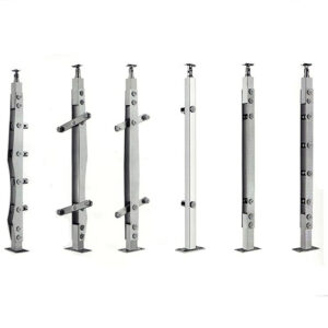
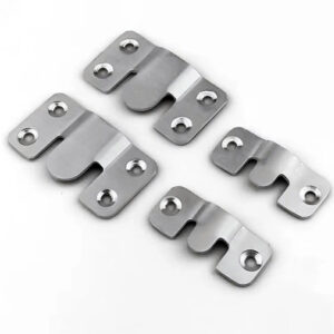
For hardware not part of a vessel’s bonded system, such as stainless steel mounting brackets and cleats, the goal is complete electrical isolation. This requires insulating the hardware from its substrate (e.g., a concrete dock or an aluminum rail) using phenolic or composite pads, and using isolated, non-conductive fasteners or insulating sleeves for all bolts. The entire assembly must be kept free of conductive debris or metallic paint splatter that could create a bridge. This method is highly effective but demands meticulous attention during installation and periodic inspection.
Using Sacrificial Anodes for Cathodic Protection
The Principle of Intentional Sacrifice
Cathodic protection (CP) intentionally introduces a third, less noble metal into the circuit to act as a consumable anode. Metals like zinc or aluminum are electrically connected to the protected structure (the cathode) and immersed in the same electrolyte. They corrode sacrificially, generating a protective current that suppresses corrosion on all connected metals. This is a proactive method of controlling the electrochemical reaction, effectively making the entire protected structure a cathode.
A Critical Insight for Stainless Steel
A key strategic insight is that stainless steel underwater often requires cathodic protection to prevent its own forms of corrosion. While noble, stainless steel is susceptible to crevice corrosion and pitting in oxygen-depleted areas. Connection to a sacrificial anode provides a small protective current that helps stabilize its passive oxide layer, preventing localized breakdown. Therefore, specifying stainless steel for submerged service frequently necessitates bonding it to an anode system, which contradicts the instinct to electrically isolate it. This duality is central to effective marine design.
Material Selection and System Design
Selecting the correct anode material is critical. The following table outlines the primary options and their applications, based on authoritative engineering practice.
Sacrificial Anode Selection Guide
| Anode Material | Primary Application | Key Consideration |
|---|---|---|
| Zinc | Saltwater vessels | Traditional choice |
| Aluminum | Salt/Brackish water | Higher capacity |
| Magnesium | Freshwater only | Too active for salt |
Source: ISO 13174 – Cathodic protection of harbour installations (https://www.iso.org/standard/67729.html). This standard specifies requirements for cathodic protection systems in seawater, including material selection, design, and installation of sacrificial anodes for steel structures, principles directly applicable to protecting marine hardware.
Note: Stainless steel underwater often requires anodes to stabilize its passive oxide layer.
The anode must be sized correctly based on the wetted surface area of the protected cathode, the desired protection current density, and the required lifespan. Anodes must be bonded with robust, low-resistance connections and placed to ensure even current distribution. They require regular inspection and replacement once consumed beyond a specified percentage.
Marine-Specific Challenges: Crevice and Stray Current Corrosion
The Threat of Crevice Corrosion
Crevice corrosion is a localized attack on stainless steel that occurs in shielded, stagnant areas where oxygen is depleted—under gaskets, washers, or marine growth. This oxygen starvation causes a breakdown of the protective passive layer within the crevice, leading to aggressive pitting. Prevention requires designs that minimize crevices, the use of non-absorbent gaskets, and the application of sealants to exclude water. Ensuring water flow and preventing sediment buildup are also key maintenance activities.
The Rapid Failure of Stray Current Corrosion
Stray current corrosion is a distinct, often rapid failure mechanism caused by DC electrical faults, not material dissimilarity. Faulty onboard wiring, bilge pump circuits, or shore-power systems can leak direct current into the water, using an immersed metal fitting as an unintended anode. This can dissolve a through-hull fitting or propeller shaft in a matter of weeks. Prevention hinges on proper marine-grade electrical installation, insulation, and the mandatory use of galvanic isolators or isolation transformers on all shore power connections.
Differentiating and Mitigating Combined Threats
These marine-specific threats often coexist with galvanic corrosion, complicating diagnosis. The following table helps differentiate the primary causes and prevention methods for these interconnected risks.
Marine Corrosion Threat Matrix
| Threat | Primary Cause | Prevention Method |
|---|---|---|
| Crevice Corrosion | Stagnant, oxygen-poor water | Design to avoid crevices |
| Stray Current Corrosion | DC electrical system faults | Install galvanic isolator |
| Galvanic Corrosion | Dissimilar metal contact | Material compatibility |
Source: NACE SP0176 – Control of Corrosion on Steel, Fixed Offshore Platforms Associated with Petroleum Production. This standard practice addresses comprehensive corrosion control in marine environments, including mitigation strategies for galvanic, crevice, and stray current corrosion on offshore structures.
Note: Galvanic isolators/transformers are essential for docked vessels.
Accurate failure analysis is critical. A pitted fitting might result from galvanic action, crevice conditions, or stray current. Misdiagnosis leads to ineffective remediation. Marine maintenance teams need training to identify telltale signs, such as the pattern of attack or correlation with electrical system use.
Material Selection and Galvanic Series Compatibility
The Foundation: The Galvanic Series
Material selection is the cornerstone of corrosion prevention. Engineers must reference a galvanic series chart specific to seawater, which ranks metals by their electrochemical potential. The goal is to select metals that are close together on this series to minimize the driving force for corrosion. For example, coupling stainless steel with a more active metal like aluminum or mild steel requires careful management, while coupling it with a more noble metal like bronze or titanium poses a high risk unless the anode area is very large.
Applying the Series in Design
The following table provides a simplified galvanic series for common marine metals, serving as a fundamental reference for material pairing decisions.
Galvanic Series for Seawater
| Metal (in Seawater) | Galvanic Potential (Relative) | Compatibility with Stainless Steel |
|---|---|---|
| Zinc (Anode) | Most Active (-1.05V) | Excellent (Sacrificial) |
| Aluminum | Active (-0.9V) | Good (Sacrificial) |
| Mild Steel | Active (-0.7V) | Acceptable (Anodic) |
| Stainless Steel | Noble (-0.5V) | Reference Point |
| Bronze | More Noble (-0.3V) | Risky (Cathodic to SS) |
| Titanium | Most Noble (-0.1V) | High Risk (Strong Cathode) |
Source: ASTM G82 – Guide for Development and Use of a Galvanic Series for Predicting Galvanic Corrosion Performance. This standard provides the fundamental framework for ranking metals by their electrochemical potential in a given electrolyte, which is the basis for predicting galvanic corrosion risk and selecting compatible material pairs in marine environments.
Note: A small anode (e.g., aluminum fastener) connected to a large cathode (e.g., stainless plate) leads to rapid corrosion.
The critical design rule derived from this is to never couple a small, active anode to a large, noble cathode. If dissimilar metals must be used, the design should ensure the anodic metal has a much larger surface area. This principle is non-negotiable for hardware like fasteners, where specifying an aluminum bolt for a stainless steel plate is a design flaw.
The Reality of Seawater Conductivity
A frequently underestimated factor is the marine environment itself. Saltwater’s high ionic conductivity dramatically accelerates galvanic corrosion compared to fresh or brackish water. This reality demands that marine hardware standards, inspection intervals, and maintenance schedules be exponentially more rigorous. Material choices and protection strategies acceptable for freshwater applications will fail prematurely in a full saltwater service.
Implementation and Maintenance Best Practices
Documentation and Consistent Strategy
Successful implementation begins with a documented corrosion control plan. This plan should clearly state the electrochemical philosophy (bonded vs. isolated) for the asset and specify all materials, isolation components, coating systems, and anode details. Consistency is paramount; mixing bonded and isolated components on the same structure can create dangerous galvanic cells. All installation personnel must be briefed on this plan to ensure uniform execution.
Systematic Inspection and Maintenance
Maintenance is not optional; it is a scheduled engineering function. Sacrificial anodes must be inspected annually for consumption and replaced when 50-70% depleted. Insulating gaskets and coatings require visual inspection for cracking, compression set, or physical damage. Electrical bonding connections should be checked for continuity and low resistance. A common mistake is only inspecting anodes; the entire isolation and bonding system must be assessed as an integrated unit.
Accurate Diagnosis for Effective Remediation
When corrosion occurs, accurate diagnosis dictates the correct remediation. Is it localized pitting under a fitting (crevice)? Is it rapid, general wastage on a single component (stray current)? Or is it corrosion focused at the junction of two metals (galvanic)? Each has a different fix. Spare parts kits should include not just hardware, but the correct isolation kits and sealants specified in the original plan. Reactive replacement without diagnosis often repeats the failure.
A Decision Framework for Protecting Your Hardware
A Stepwise Engineering Approach
Protecting marine hardware requires a systematic, stepwise framework that integrates all previous strategies. This structured approach ensures no critical layer of defense is omitted during design or installation.
Systematic Corrosion Prevention Framework
| Step | Action | Key Principle |
|---|---|---|
| 1. Material Selection | Reference galvanic series chart | Minimize potential difference |
| 2. Electrical Isolation | Use insulating gaskets/coatings | Break electrical contact path |
| 3. Cathodic Protection | Install/bond sacrificial anodes | Introduce consumable anode |
| 4. Address Marine Threats | Eliminate crevices; use isolators | Defense-in-depth strategy |
Source: DNVGL-RP-0416 – Corrosion protection for ships. This recommended practice provides a systematic framework for corrosion protection, integrating material selection, isolation, cathodic protection, and specific threat mitigation for marine vessels and hardware.
Following this framework forces disciplined decision-making. First, select the most compatible materials possible. Second, implement electrical isolation in all assemblies as a primary barrier. Third, integrate sacrificial anodes where stainless steel is submerged or in a bonded system. Fourth, design out crevices and install galvanic isolators on shore power to address endemic marine threats.
Context Dictates Strategy
The operational context finalizes the strategy. For an integrated vessel, a bonded cathodic protection system is typically central. For standalone dock infrastructure, complete electrical isolation is the goal. The wrong choice for the context guarantees problems. Looking forward, advanced ceramic nano-coatings that provide durable, non-conductive barriers and resist biofouling without biocides represent a significant technological evolution, especially as environmental regulations on traditional anti-foulants tighten.
Effective corrosion management transforms stainless steel from a potentially vulnerable material into a durable, long-lasting solution. It requires moving from component selection to system design, where electrochemical principles guide every installation detail. The priority is implementing a documented, multi-layered defense strategy from the outset, backed by a disciplined inspection regimen.
Need professional-grade stainless steel hardware and integrated corrosion management solutions? The engineers at Esang specialize in providing marine-rated components and technical guidance for complex installations, ensuring your specifications align with proven electrochemical protection strategies.
For direct consultation on your specific application requirements, you can Contact Us.
Frequently Asked Questions
Q: How do you decide between electrically bonding or isolating stainless steel hardware on a vessel?
A: Your decision depends on the hardware’s integration. For a vessel’s bonded system, connect all major underwater metals to a common sacrificial anode via heavy-gauge wire to equalize potential. For standalone hardware like a dock cleat, aim for complete electrical isolation using non-conductive gaskets and coatings. This means you must adopt a single, documented electrochemical strategy for the entire asset to avoid contradictory practices that accelerate corrosion.
Q: What is the critical design rule for pairing dissimilar metals in seawater?
A: The most critical rule is to ensure the anode’s surface area is significantly larger than the cathode’s. A small anode connected to a large cathode will corrode with alarming speed. You must reference a seawater galvanic series chart to minimize the electrochemical potential difference between metals. For projects where you must use a less noble fastener on a noble plate, you should oversize the fastener or use isolation to mitigate the severe risk.
Q: Why would you connect sacrificial anodes to stainless steel if it’s a noble metal?
A: You connect sacrificial anodes to stainless steel because, while noble, it is susceptible to pitting in oxygen-depleted crevices. Bonding it to a less noble metal like zinc or aluminum provides cathodic protection that stabilizes stainless steel’s protective passive layer. This means using stainless steel underwater frequently necessitates integrating it into an anode system, which contradicts the instinct to isolate it but is essential for long-term integrity. Relevant practices are outlined in standards like ISO 13174.
Q: How do you prevent stray current corrosion on a vessel connected to shore power?
A: You prevent it by installing essential protective devices on the shore power connection. Galvanic isolators or isolation transformers are mandatory capital equipment for docked vessels, as they block damaging DC currents from faulty electrical systems. Proper onboard electrical installation is also critical. If your vessel operates from a marina, plan for this equipment in your capital budget, as it protects both your hardware and the marina’s infrastructure from rapid, severe dissolution.
Q: What are the best materials and methods for achieving electrical isolation between metals?
A: Use non-conductive, non-absorbent barriers like plastic, rubber, or composite insulating washers and gaskets at all joining surfaces. Applying robust, non-porous coatings such as epoxy or specialized marine primers to the more noble metal before assembly is equally vital. Your procurement specifications must explicitly list these components as non-optional. For installations where complete isolation is the goal, expect to implement both mechanical barriers and coatings as a combined defense layer.
Q: What maintenance practices are non-negotiable for a marine corrosion protection system?
A: You must regularly inspect sacrificial anodes for consumption and replace them promptly. Also, check insulating coatings and gaskets for damage during routine surveys. A critical practice is accurate failure analysis to differentiate galvanic corrosion from stray current corrosion, as misdiagnosis leads to ineffective fixes. This means marine maintenance teams require specific training and diagnostic tools to correctly identify corrosion mechanisms and apply the proper remediation.
Q: How does saltwater change the corrosion risk compared to freshwater installations?
A: Saltwater’s high ionic conductivity dramatically accelerates galvanic corrosion, increasing the driving force for electrochemical degradation. This makes the electrolyte far more aggressive than freshwater. Consequently, you must apply exponentially more rigorous material standards, design rules, and maintenance schedules. For projects in marine environments, simply transferring freshwater engineering practices guarantees premature hardware failure and necessitates a dedicated, multi-layered defense strategy from the outset.