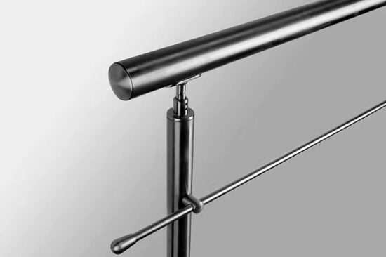
For architects, engineers, and contractors, specifying a stainless steel handrail that meets the 200-pound load capacity requirement is a fundamental safety and compliance task. Yet, the critical error is treating this as a simple material check. The real challenge is designing a complete system where every component—from the rail to the substrate—works in concert under combined loads, without a single point of failure.
This systemic approach is non-negotiable now. Building inspections are rigorous, and liability for failure is severe. A handrail is life-safety infrastructure. Its design requires synthesizing material science, structural mechanics, and certified hardware data into a verified assembly that performs for decades.
Core Load Requirements and Design Principles Explained
Understanding the Dual Load Mandate
Building codes don’t specify a single test. The IBC 2021 International Building Code mandates that guards and handrails resist a 200-pound concentrated load applied in any direction and a uniform live load of 50 pounds per linear foot, applied simultaneously. This dual requirement simulates a person falling against the rail while others lean on it. Designing for only one scenario is a common, non-compliant shortcut.
The Role of the Safety Factor
The material’s published yield strength is not the allowable design stress. A safety factor between 1.67 and 2.5 is applied to account for load uncertainties, material imperfections, and long-term durability. For Type 304 stainless with a 30 ksi yield, the allowable stress could be as low as 18 ksi (30 / 1.67). This factor ensures the system has reserve capacity beyond the minimum code, a crucial distinction between a theoretical and a reliable design.
System vs. Component Thinking
The strategic implication is clear: load capacity is a chain. Its strength is defined by the weakest link, which is often the field connection or the existing structure. Therefore, procurement must be for a complete, engineered system with specified components. Value engineering that substitutes unrated hardware compromises the entire assembly’s certified rating and creates significant liability exposure.
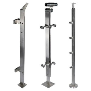
Key Components in the Load Path Analysis
The Load Transfer Chain
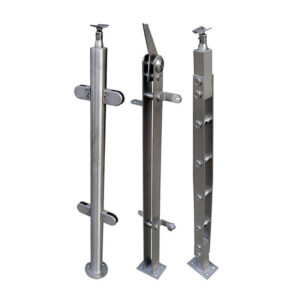
A 200-pound force applied to the rail follows a defined path: 1) The rail span bends, transferring load to the posts. 2) Posts act as cantilevers, creating high moment and shear at their base. 3) Mounting hardware (base plates, anchors) resists pull-out and shear. 4) The substrate (concrete, steel) must absorb these forces. A holistic analysis validates each link.
Identifying the Critical Connection
In practice, the connection at the post base is most vulnerable. It must resist a prying action from the cantilever moment. This is where specifying generic anchors instead of tested, rated components leads to failure. The substrate’s capacity—often overlooked—is equally critical. Installing a high-strength anchor into weak concrete negates its rated value.
The Procurement Imperative
This analysis underscores why you cannot mix and match components from different suppliers without engineering review. The post-to-base plate connection, bolt torque, and anchor embedment depth are interdependent variables in a tested assembly. Specifying a complete stainless steel handrail mounting system from a single source ensures these interfaces are pre-validated.
Step-by-Step Calculation Methodology
Establishing the Framework
A systematic calculation synthesizes loads, geometry, and material properties. First, define all parameters: load cases per ASCE/SEI 7-16, material yield strength, member dimensions, and span. Second, identify the worst-case scenario, typically the 200 lb load at the mid-span of the longest rail section.
Analyzing Rail and Post Stresses
The rail is analyzed as a simply supported beam for bending stress (σ = M/S) and deflection (δ = (P * L³) / (48 * E * I)). The post is modeled as a cantilever; the reaction force from the rail, multiplied by the post height, creates the design moment at its base. Both stresses must be below the material’s allowable stress.
Synthesizing for System Validation
The final step is designing the connection. The base moment creates tension in the windward anchor bolts. You must calculate this tension (T = M_base / bolt spacing) and the direct shear, then select anchors whose published allowable values exceed both. This synthesis of disparate calculations is precisely why professional engineering stamp is required for commercial applications.
Material Considerations and Safety Standards
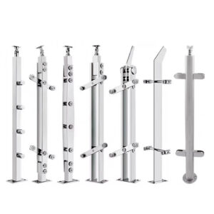
Grade Selection and Mechanical Properties
Material choice dictates the fundamental design values. Austenitic stainless steels like Type 304 and 316 are common. Their minimum yield strength, as defined by standards like ASTM A554, is the starting point for stress calculations. Cold-working can increase yield strength, offering potential for more slender profiles but requiring verified mill certificates.
Navigating the Standard Hierarchy
Design is governed by an interlinked hierarchy of standards. The IBC is the law. It references ASCE 7 for loads and AISC 370-21 Specification for Structural Stainless Steel Buildings for member design. ASTM standards define material properties. A compliant design actively references this chain of authority.
The Cost-Performance Balance
Material and finish selection carry direct cost implications. While Type 316 offers superior corrosion resistance for harsh environments, its premium over Type 304 may not be justified indoors. Value engineering must balance environmental needs with load requirements and budget, as the material grade directly affects the allowable stress and, therefore, the required member size.
Core Load Requirements and Design Principles Explained
| Load Case | Required Load | Application |
|---|---|---|
| Concentrated Load | 200 pounds | Any point on rail |
| Uniform Live Load | 50 lbs/ft | Entire rail length |
| Combined Analysis | Both loads simultaneously | Mandatory for compliance |
| Safety Factor Range | 1.67 to 2.5 | Applied to material strength |
Source: ASCE/SEI 7-16 Minimum Design Loads for Buildings and Other Structures. This standard establishes the minimum uniform and concentrated live loads for guards and handrails, which are the fundamental design criteria referenced by the IBC.
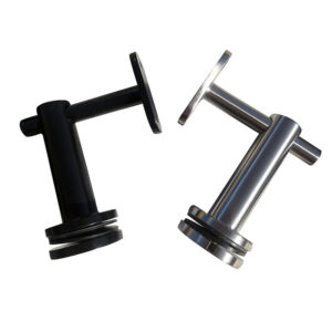
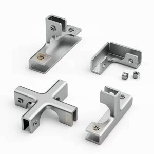
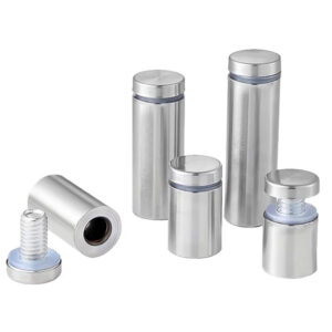
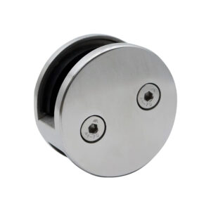
Selecting the Right Mounting Hardware and Anchors
Hardware as a Certified Component
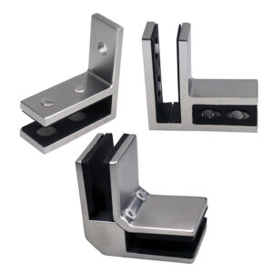
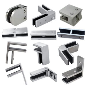
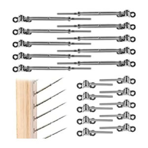
Mounting hardware is not generic. Each bolt, anchor, and base plate has a specification sheet tied to a specific part number, material, and finish. These sheets provide the critical allowable tension and shear values for calculation. Substituting a visually similar anchor from a different manufacturer invalidates the system’s engineering assumptions.
Analyzing Anchor Failure Modes
Anchors must be checked for concrete breakout strength in tension and shear, which is a function of embedment depth, spacing, and concrete strength. The base plate thickness must also be checked for bending under the post’s reaction load. Industry experts consistently find that field-installed anchors, without proper torque control or in substandard concrete, are the most frequent point of failure.
The Specification Imperative
This highlights the strategic need for strict adherence to the component schedule from the engineered design. Using only specified parts maintains warranty coverage and ensures the installed system matches the tested assembly’s performance. It transforms the hardware from a commodity into a life-safety component.
Selecting the Right Mounting Hardware and Anchors
| Failure Mode | Critical Check | Data Source |
|---|---|---|
| Anchor Pull-Out (Tension) | Calculated Tension vs. Allowable | Manufacturer’s specification sheet |
| Anchor Shear | Calculated Shear vs. Allowable | Manufacturer’s specification sheet |
| Base Plate Bending | Under post reaction moment | Engineered design drawings |
| Substrate Capacity | Concrete/structural strength | Site inspection & core tests |
Source: Technical documentation and industry specifications. Anchor capacity is product-specific and must be verified using the manufacturer’s published technical data for the exact substrate and installation conditions.
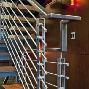
Practical Example: Calculating a 4-Foot Span System
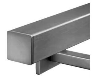
Defining the Scenario
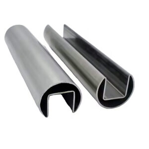
Consider a common scenario: a 1.5-inch square Type 304 tube rail (0.125-inch wall) supported by 2-inch square posts at 4-foot (48-inch) centers, with a post height of 42 inches. The goal is to check the system for the 200 lb mid-span load.
Performing the Calculations
First, calculate the rail’s bending moment: M = (P * L) / 4 = (200 lb * 48 in) / 4 = 2400 in-lbs. Using the rail’s section modulus (S), find the bending stress (σ = M/S) and verify it is below the allowable (e.g., 18 ksi). Next, the post base moment: Assuming a 100 lb reaction from the rail, M_base = 100 lb * 42 in = 4200 in-lbs. This moment must be checked against the post’s capacity.
Designing the Connection
For a base plate with two bolts spaced 4 inches apart, the moment induces tension in the windward bolt: T ≈ M_base / bolt spacing = 4200 in-lbs / 4 in = 1050 lbs. This tension, combined with shear, dictates the anchor selection. In my experience, this bolt tension value often surprises designers, revealing why connections fail if not properly calculated.
Practical Example: Calculating a 4-Foot Span System
| Component | Parameter | Example Value / Calculation |
|---|---|---|
| Rail Span (L) | 4 feet | 48 inches |
| Rail Bending Moment (M) | M = (P * L) / 4 | (200 lb * 48 in) / 4 = 2400 in-lbs |
| Post Height | 42 inches | – |
| Post Base Moment | M_base = R * H | 100 lb * 42 in = 4200 in-lbs |
| Anchor Bolt Tension | T = M_base / Bolt Spacing | Depends on plate design |
Source: IBC 2021 International Building Code. The IBC mandates compliance with load requirements and references the material and design standards (ASCE 7, AISC) used to perform these example calculations.
Common Design Mistakes and How to Avoid Them
Overlooking Serviceability (Deflection)
A rail can be strong enough but feel unsafe if it deflects too much. Deflection often governs design before strength does. The typical limit is L/180 or 0.5 inches. A flexible rail can loosen connections over time. Always calculate deflection (δ = (P * L³) / (48 * E * I)) as a primary check.
Inconsistent Application of Standards
Mixing load factors from one standard with resistance factors from another creates a non-conservative, non-compliant design. Use a consistent set of standards—IBC, ASCE 7, and AISC 370—throughout the entire calculation. Easily overlooked details include the required direction of the concentrated load (any direction, not just downward).
Field Verification Gaps
The greatest exposure is assuming the substrate matches design assumptions. Always validate existing concrete strength and condition. Specify installation procedures, including required torque for mechanical anchors and proper hole cleaning for adhesive anchors, in the project documents to bridge the design-installation gap.
Step-by-Step Calculation Methodology
| Step | Key Parameter | Formula / Check |
|---|---|---|
| 1. Define Properties | Material Yield Strength | e.g., 30 ksi (304 SS) |
| 2. Worst-Case Scenario | 200 lb load | Mid-span between posts |
| 3. Rail Bending Stress | σ = M / S | vs. Allowable Stress (e.g., 18 ksi) |
| 4. Rail Deflection | δ = (P * L³) / (48 * E * I) | vs. Limit (e.g., L/180) |
| 5. Post Base Moment | M_base = Reaction * Height | Check post capacity |
Source: AISC 370-21 Specification for Structural Stainless Steel Buildings. This specification provides the design strengths, allowable stresses, and stability requirements for structural stainless steel members, which are used in steps 1, 3, and 5.
Next Steps: Validating Your Design and Installation
For commercial or complex installations, engage a qualified structural engineer to review and stamp the design. This formal validation is a prerequisite for permits and mitigates liability. On-site, conduct a pre-installation meeting to review substrate conditions and torque procedures with the installers.
Treat handrails as critical infrastructure with a lifecycle. Mandate a maintenance schedule that includes periodic inspection of fasteners and connections for corrosion or loosening. The as-built load capacity degrades without upkeep.
Ultimately, a safe, compliant handrail system results from three priorities: a holistic design that analyzes the complete load path, strict adherence to specified components, and rigorous field validation. This integrated approach transforms a code minimum into a durable safety asset.
Need professional engineering support or certified stainless steel handrail systems? Esang provides engineered solutions and components designed for compliance and durability. For specific project inquiries, you can also Contact Us.
Frequently Asked Questions
Q: What are the actual live load requirements for a commercial stainless steel handrail?
A: Building codes mandate that handrails must resist two simultaneous loads: a 200-pound concentrated force applied at any point and a uniform live load of 50 pounds per linear foot. This dual requirement, specified in standards like ASCE/SEI 7-16 Minimum Design Loads for Buildings and Other Structures, ensures safety against both a single impact and crowd pressure. This means your structural analysis must validate both load cases concurrently, not separately, to achieve compliance with the IBC 2021 International Building Code.
Q: How do you calculate the load capacity for a stainless steel handrail post?
A: Model the post as a cantilever beam. Calculate the reaction force from the rail loads, then multiply it by the post height to find the bending moment at the base. You must then check that the resulting stress is below the material’s allowable limit, which for Type 304 stainless is its yield strength divided by a safety factor of 1.67 to 2.5, as defined in AISC 370-21 Specification for Structural Stainless Steel Buildings. For projects with tall railings, expect post base connection design to be the governing factor, not the rail itself.
Q: Why is the mounting hardware the most critical component in a handrail system?
A: The hardware forms the final, vulnerable link in the load path, transferring all forces into the building structure. Its capacity in tension and shear, based on concrete strength and anchor specifications, often determines the system’s ultimate safety. Substituting unrated or generic hardware invalidates the engineered design’s certification. This means you must procure and install only the exact components listed in the specification sheets to maintain liability protection and warranty coverage.
Q: What is a common calculation mistake when designing handrail spans?
A: A frequent error is designing only for strength while ignoring serviceability limits like deflection. Excessive flex, often limited to span length divided by 180 (L/180), can make a rail feel unsafe and stress connections prematurely. You must perform deflection calculations using the rail’s moment of inertia and material modulus of elasticity alongside stress checks. For long spans in commercial settings, deflection criteria will typically govern the design before material strength does.
Q: How do material choices like stainless steel grade affect handrail design and cost?
A: The stainless steel grade, such as Type 304 or 316, defines the yield strength used in your stress calculations, directly impacting member sizing. While cold-working can increase strength, the allowable stress is the yield strength divided by the safety factor. This material selection carries a direct cost premium over alternatives like carbon steel. Therefore, value engineering must balance corrosion resistance needs with structural requirements and budget, as the choice affects both the engineering values and total project cost.
Q: What steps are needed to validate a handrail design after calculations are complete?
A: Validation requires a professional structural engineer’s review and stamp for commercial applications. On-site, you must inspect the substrate (concrete slab or wall) to confirm it can handle the anchor loads. During installation, strictly follow the manufacturer’s torque specifications for all fasteners. This process means you should budget for both engineering review and qualified installation labor, as field errors are the primary point of failure for an otherwise sound design.
Q: What ongoing maintenance is required for handrail load capacity?
A: Handrail systems require lifecycle maintenance, as their as-built capacity can degrade from vibration, corrosion, or loosened fasteners. Implement a scheduled inspection program to check anchor tightness, base plate integrity, and material condition. This means owners should treat handrails as critical safety infrastructure with recurring costs, not a one-time capital expense, to ensure long-term compliance and safety.