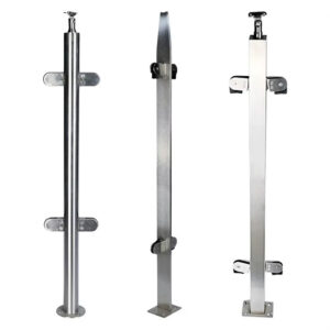
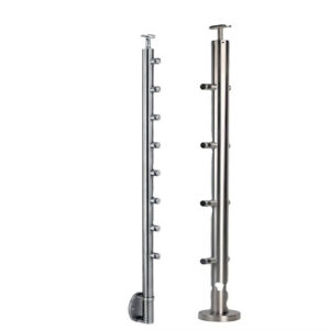
A drain detail that looks complete on paper can still fail in service if the water it collects has nowhere accessible to go once it reaches the real, installed orientation of the railing. Reviewing a drawing for waterfront railing drainage means tracing the path water and salt actually take through bases, sleeves, caps, joints, and crevices, then asking whether that path stays open and inspectable once the hardware is built and anchored in place.
Tracing water and deposit paths through the actual railing detail
A drainage detail only means what it shows when it is read against the real orientation of the installed railing, not the idealized section view used to generate it. Water does not move according to the logic of a drawing; it follows gravity, surface tension, and whatever gaps or ledges the assembled hardware presents at its actual tilt, slope, and exposure. A path that appears continuous in a straight vertical section can terminate at a horizontal ledge, a change in component angle, or a shouldered interface once the same detail is read in the orientation it will actually occupy on site.
This matters because the same base plate, sleeve, or cap can behave differently depending on whether the post is plumb, raked, or stepped along a sloped walking surface, and whether the railing sits at the immediate waterline or at a setback from spray and splash. Where the installed orientation changes the angle at which water approaches a joint or recess, the point at which it collects also changes, even though the component geometry on the shop drawing is identical. A reviewer who checks only the generic section misses this; a reviewer who traces the path through the specific orientation of the specific run catches it.
Tracing the path also means following it past the component the drawing emphasizes. A base plate detail that shows water leaving the plate is not complete until the drawing also shows where that water goes next: onto a deck surface, into a channel, against a dissimilar material, or into a concealed cavity. The same logic applies at sleeves, caps, rail joints, and fastener recesses. Each is a point along a path, not an endpoint, and the review question at each one is whether the path keeps moving or whether it stops at that location.
Where a project includes soluciones de barandillas para zonas ribereñas as part of its coastal or marine-adjacent scope, this tracing exercise becomes the basis for every other check in the review. Downstream decisions about collection points, drain-outlet coordination, and inspection access all depend on having first established, for the actual installed geometry, where water enters the assembly and where it is supposed to leave it. Skipping this step and checking components in isolation produces a review that looks thorough but has not actually confirmed continuity of the path.
Base plates, sleeves, caps, and fastener recesses that can retain moisture
| Detail location | Accumulation condition to check | Drawing or inspection question |
|---|---|---|
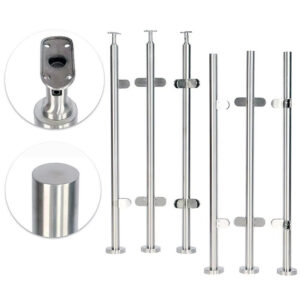
| Placas de base | Water, salt, or debris held at horizontal ledges or the base interface | Does the actual orientation show a clear path away from the base without hiding the discharge at the supporting interface? |
| Sleeves | Water or deposits remaining in a pocket around the sleeve | Is the outlet path coordinated with waterproofing and the supporting structure, and can the pocket be reached for cleaning? |
| Caps | Sealed pockets where moisture or deposits can remain between cleaning cycles | Does the detail show whether the pocket drains and whether inspection access is available? |
| Fastener recesses | Salt or debris retained in sheltered recesses | Can the recess be inspected and cleaned in the installed orientation? |
These four locations share a structural role in drainage review: each is a point where hardware geometry can either let water keep moving or hold it in place. The mechanism is the same at each location even though the geometry differs. A horizontal surface, a sealed or partially sealed cavity, or a recess sized to fit a fastener head rather than to shed water all create conditions where moisture and airborne salt can remain in contact with the metal and any adjoining material for longer than an open, sloped, or ventilated surface would allow.
Placas de base raise this question at the interface between the railing and the supporting structure. Where the plate sits flush against a deck or slab with no relief, water arriving at the plate has to find an exit path around or through the fastening pattern; if that exit is not shown, the drawing has not established that water actually leaves the base rather than sitting beneath it. The same base plate detail that works on a sloped, open deck can behave differently where the surrounding substrate is level, because the surrounding condition, not the plate alone, determines whether gravity does the work.
Sleeves introduce an annular gap around the post, and that gap is a pocket whether or not it was designed to be one. Where the sleeve is coordinated with a grout or sealant fill and a drain path out of the annulus, the pocket empties. Where it is not, the same gap that accommodates installation tolerance also accommodates standing water and salt between the sleeve and the post.
Caps are frequently treated as closures rather than as drainage features, which is precisely why they warrant separate review. A cap that seals a hollow post against surface water intrusion can simultaneously create a sealed pocket at its own underside or perimeter if it is not vented or sloped to shed condensation and incidental moisture that reaches it from inside the section.
Fastener recesses combine a sheltered geometry with a dissimilar-material interface, since the fastener material, washer, or sealant at the recess is rarely identical to the surrounding stainless hardware. Where the recess is also shielded from direct wash by rain or maintenance cleaning, deposits can remain there between cleaning cycles even when the surrounding open surfaces are being rinsed regularly.
Hollow sections, rail joints, weld areas, and sheltered crevices
Hollow sections, joints, weld areas, and crevices extend the same retention logic into locations that are connected to each other rather than isolated, which changes how a reviewer has to think about them. A hollow rail or post is not a single enclosed volume in practice; it has openings at caps, joints, drilled holes, and fastener penetrations, and water or humid air can move between these openings along the inside of the section. A detail that addresses one opening without considering the others may close one entry point while leaving the hollow interior connected to a different unaddressed opening elsewhere along the run.
Rail joints and weld areas introduce a second mechanism alongside geometry: a change in surface continuity. A weld toe, a mechanical joint, or a transition between two formed sections is a location where the finished surface is no longer a single uninterrupted plane, and that discontinuity can create a ledge, a crevice, or a capillary gap even where the surrounding sections are smooth and self-draining. Where the joint is also where two different manufacturing processes meet, the surface condition at that exact line can differ from the surrounding material even when the alloy specification is the same, which affects how readily moisture is retained at that line rather than running past it.
Sheltered crevices are the general condition that base plates, sleeves, caps, recesses, joints, and welds can all produce under the right geometry, and that is why they are treated here as a category rather than a single location. A crevice does not need to be large to function as a retention point; it needs only to be narrow enough and sheltered enough that neither rainfall nor routine washing reaches the full depth of the gap. Where a crevice sits in a location exposed to direct wash, the same narrow gap behaves differently than where it sits in a sheltered position protected by an overhang, a handrail profile, or the orientation of the post itself.
For the reviewer, the practical consequence is that these connected features cannot be checked one at a time without also checking the connections between them. A joint that drains on its own can still feed a sealed hollow section below it; a weld area that sheds surface water can still leave a crevice at its toe that does not. The review question at this stage is not whether each individual feature drains, but whether the combination of features along the full connected path does.
Waterproofing and substrate interfaces affected by drain outlets
A drain outlet is only as effective as the interface it discharges into, and that interface sits outside the railing hardware itself, at the boundary with waterproofing membranes, flashing, deck surfaces, or other substrate elements the railing is anchored to or passes through. This is the point in the review where drainage stops being purely a hardware question and becomes a coordination question between the railing supplier’s components and the surrounding construction.
The underlying mechanism is straightforward: moving water out of a base plate, sleeve, or hollow section accomplishes nothing if the water is simply redirected into a different enclosed or inaccessible space. Where a drain outlet discharges onto an open, sloped, finished surface, the water continues moving and the detail has done its job. Where the same outlet discharges against an unsloped substrate, into a gap behind flashing, or into a cavity that has no further path to daylight, the drainage detail has relocated the retention problem rather than resolved it.
This is also where waterproofing continuity becomes relevant. A penetration through a waterproofed deck or terrace surface, such as a sleeve or anchor penetration, requires the waterproofing detail and the railing drain outlet to be coordinated as a single system rather than designed independently. Where the railing manufacturer’s drainage path assumes an open discharge point but the waterproofing detail routes water differently at that exact location, the two details can conflict even though each one is correct in isolation.
The supporting structure introduces a related condition: a substrate with its own slope, drainage, and material transitions can either reinforce or undermine a railing’s drain outlet depending on how the two align. Where the project team confirms the elevation and slope of the substrate at each outlet location, the drain outlet can be evaluated against where water goes after it leaves the railing hardware, not only whether it leaves the hardware. This confirmation sits with the project team coordinating structure, waterproofing, and railing scope together, since no single trade’s detail resolves the interface on its own.
Cleaning and inspection access for removing collected debris
A drainage path that is theoretically open still depends on an outlet, joint, or recess remaining clear of the debris, salt deposits, and biological growth that collect at exactly the locations identified earlier. Drainage and access are therefore linked: a detail that routes water correctly but conceals the point where debris collects has solved only part of the problem, because the same geometry that lets water drain under design conditions can become blocked once deposits accumulate, and a blocked path behaves like a closed one.
The mechanism here concerns visibility on the drawing rather than a hidden property of the hardware itself. A base plate interface, a sleeve annulus, or a cap underside can be fully specified for drainage and still leave no indication, on the drawing or in the finished assembly, of how a maintenance crew would reach that location to remove accumulated material. Where the access point is only reachable by disassembling hardware that was not intended to be removable, the practical access is effectively absent even though a path exists on paper.
Access requirements differ by location in ways that depend on exposure and shelter rather than on component type alone. An open, exposed surface that sheds most debris through rainfall and wind needs less deliberate access provision than a sheltered crevice or sealed pocket that depends entirely on manual cleaning to stay clear. Where a location is both sheltered from natural washing and difficult to reach physically, it combines the two conditions that make debris retention most consequential for drainage performance over time, and it is this combination, not either condition alone, that determines whether inspection access needs to be built into the detail from the start.
This is also a place where drawings diverge from installed reality in a specific way: a note stating that a location should be “accessible for cleaning” is not the same as a drawing that shows the physical means of reaching it. Where a reviewer treats a general access note as equivalent to a demonstrated access path, the review has accepted an intention rather than confirmed a capability. The distinction matters because the people who maintain the installation after handover will be working from the built condition, not from the design intent behind it.
Detail-release check for drainage paths, service access, and responsibility
| Release item | Evidence to see on the project detail | Release decision boundary |
|---|---|---|
| Drainage path | The actual orientation is traced through bases, sleeves, joints, fastener recesses, and hollow-section openings | Do not release the detail while the path ends at an unshown or inaccessible interface. |
| Deposit collection points | Applicable horizontal ledges, sealed pockets, dissimilar interfaces, and sheltered crevices are identified | Confirm how each applicable location remains accessible between cleaning cycles. |
| Drain outlet interface | The outlet relationship to waterproofing and the supporting structure is shown | Confirm that water is not simply redirected into an inaccessible interface. |
| Cleaning and inspection access | Access is visible on drawings wherever debris may collect | Do not release the detail if debris removal cannot be checked from the drawing. |
| Responsibility | Project-specific responsibility for drainage, waterproofing coordination, and service access is identified | Confirm responsibility before detail release. |
| Evidence boundary | Any use of ISO 9223, ASTM A380, or ASTM A967 stays within the stated classification, cleaning, or passivation scope | Do not treat these references as grade selection, structural proof, component-life prediction, or proof of a long-term coastal outcome. |
Releasing a drainage detail for construction means confirming that the path, the collection points, the outlet interface, and the access provisions have each been checked against the installed orientation, not that each component has been specified individually. The release decision sits at the intersection of these items: a detail can satisfy every component-level requirement and still fail at release if the path between components has not been confirmed as continuous and accessible.
Responsibility is part of this release check because drainage performance depends on coordination across trades, as established at the waterproofing and substrate interface. Where the railing supplier’s scope ends at the hardware and the waterproofing, substrate slope, or finished-surface drainage sits with another party, the release check needs to identify who confirms each piece of the path, not assume that specifying the railing hardware correctly discharges that responsibility for the whole assembly. ESANG’s role in this process is to work from the project-specific orientation, substrate conditions, and glass or railing configuration the buyer supplies when a detail is being reviewed or quoted; the supplier can match hardware to those stated conditions, but the buyer’s project team remains the party confirming how the hardware interfaces with the surrounding waterproofing and structure on that specific project.
Any reference to corrosion classification, cleaning procedures, or passivation treatment at this stage needs to be read within its own boundary. ISO 9223 classification of atmospheric corrosivity describes environmental severity using factors such as wetness and airborne salinity; it establishes a classification context and does not itself select a steel grade or predict how long a specific component will perform in a specific installed condition. ASTM A380 addresses cleaning, descaling, and cleanliness assessment of stainless steel surfaces, including weld areas and contamination from iron, but it does not establish structural performance or dictate a single required cleaning sequence for every project. ASTM A967 covers chemical passivation treatments and qualitative confirmation that contaminant iron has been removed, but acceptance of a passivation treatment remains specific to the application, and none of these three references, individually or together, proves a long-term coastal outcome for an installed railing assembly.
Within that boundary, the release check still has a clear task: confirm that the traced path reaches a real discharge point, that identified collection locations remain reachable for cleaning, that the drain outlet’s relationship to waterproofing and structure has been shown rather than assumed, and that someone on the project has been identified as responsible for each of these confirmations before the detail moves from reviewed to released.
Preguntas frecuentes
P: Is adding a drain hole enough to make a waterfront railing detail workable?
A: No. Trace the complete water path in the installed orientation, from each likely collection point through the outlet to a visible discharge location. Confirm that the outlet does not simply redirect water into an inaccessible waterproofing or supporting-structure interface.
P: What information should be coordinated before the drainage detail is released?
A: Show the actual orientation of relevant bases, sleeves, caps, rail joints, weld areas, fastener recesses, and hollow-section openings. The drawings should also identify outlet paths, waterproofing and substrate interfaces, cleaning and inspection access, and responsibility for resolving each interface.
P: Where is cleaning access most important in a waterfront railing system?
A: Provide access wherever water, salt, or debris may remain between cleaning cycles, including applicable horizontal ledges, sealed pockets, sheltered crevices, and recessed fasteners. Check that each location can be inspected and cleared in its installed orientation rather than assuming that drainage alone will remove deposits.
P: Why should drainage be checked in the railing’s actual installed orientation?
A: Orientation determines whether a ledge, recess, joint, or opening provides a continuous outlet or becomes a collection point. Review the assembled detail as a connected path so that drainage through one component does not end at a sealed pocket or hidden interface in another.
P: Do ISO 9223, ASTM A380, or ASTM A967 establish the correct grade or service life for a waterfront railing?
A: No. ISO 9223 provides atmospheric-corrosivity classification context, while ASTM A380 and ASTM A967 address defined cleaning or passivation scopes. These references do not by themselves select a grade, prove structural performance, predict component life, or demonstrate a long-term coastal outcome for a project.