Mounting decisions that look straightforward at the layout stage routinely become structural and waterproofing problems once drilling begins. The failure pattern is consistent: a contractor commits to a mount type based on visual preference or floor-area goals, discovers an unverifiable anchor condition mid-installation, and either proceeds with an inadequate fastener or destroys finished fascia work to correct it. The cost is not just rework—it is an inspection record that cannot be defended and a load path that was never confirmed. Understanding where each mount type creates hidden constraints, and in what sequence those constraints have to be resolved, is what allows the mount selection to hold up through installation, inspection, and long-term use.
Top and Side Mount Installation Interfaces
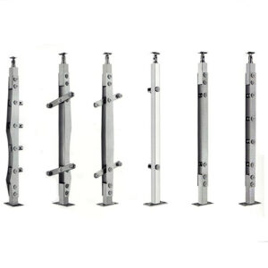
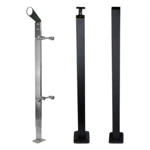
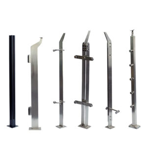
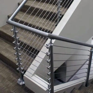
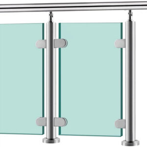
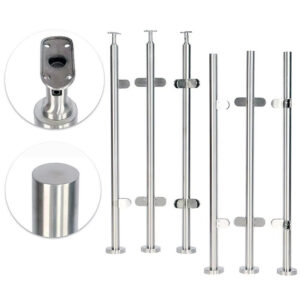
The difference between top-mount and side-mount posts is not only geometric—it is a difference in where the load enters the structure and what substrate conditions the design depends on. A top-mounted post transfers lateral load downward and outward through a base plate into the deck surface beneath it, which means the deck material, the fastener pattern, and the condition of the surface all participate in the load path. A side-mounted or fascia-mounted post transfers that load horizontally into the edge of the structure—the rim joist, blocking, or slab edge—which requires that the receiving element be both structurally adequate and accessible enough to anchor into reliably.
Neither configuration is inherently stronger. What changes is which structural condition must be verified before installation is defensible. Top mounts need a sound, level horizontal surface and a clear path for anchors that does not compromise waterproofing layers or create leak points at unflashed penetrations. Side mounts need verified edge structure with enough material depth to carry the connection, backside access where through-bolts are required, and enough edge distance from the slab or joist perimeter to keep anchors out of the splitting zone.
Both configurations also have sequencing implications. Finishes, membranes, fascia panels, and cladding all tend to close around the mounting area over the course of construction. Where those elements go in relative to railing hardware determines whether anchor conditions can still be confirmed, tightened, and inspected when the time comes. That sequencing dependency is often visible in the design drawings but ignored in the field schedule—and it is where most installation problems originate.
Edge Distance and Backside Access Failures
Side-mounting to a fascia or trim board instead of a structural rim joist or blocking is the single most common failure mode in this configuration. Fascia material is not structural regardless of thickness or fastener count. The load path requires a robust rim joist, properly sized blocking, and hardware rated for both the applied loads and the exposure conditions. Skipping that backing does not just create a marginal connection—it creates an anchor that cannot be defended under any load analysis and that may not exhibit visible distress until the railing is actually loaded.
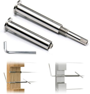
Where backside access is physically possible, through-bolts or engineered hardware should be used for guard post connections. Lag screws alone are generally insufficient for life-safety loads at these connections. ASTM E894-88(2004) provides a testing framework for evaluating anchorage adequacy in metal railing systems—useful as a reference point for what the connection is expected to resist, even where it does not prescribe a specific fastener schedule for every deck condition. The structural backing requirement and the fastener type interact: even an appropriate fastener driven into inadequate backing material does not produce an adequate connection.
The access problem compounds the verification problem. If a side-mount is installed on a raised deck where the underside is enclosed or difficult to reach, confirming bolt engagement from both sides becomes impractical during installation and nearly impossible during any subsequent inspection. The anchor is effectively hidden by geometry. This applies specifically to wood-framed conditions; it is not a universal statement about all side-mount applications, but it is the condition most likely to produce an unverifiable installation when the structural backing and access questions are not resolved in the design phase. Contractors who select fascia-mount to simplify the above-deck work often underestimate the below-deck verification they have committed to.
Inspection Access Versus Clear Walking Surface
Inspection access and usable floor area pull in opposite directions depending on which mount is chosen, and the practical weight of each factor shifts with deck height, enclosure conditions, and how the railing will be reviewed over its service life.
| Factor | Montaje superior | Montaje en salpicadero |
|---|---|---|
| Inspection ease | Easy visual inspection of base plates, flashing, and waterproofing details from deck surface | Limited access to inspect hardware and waterproofing from above; may require access from below |
| Installation on raised decks | Install from top of deck without ladders or leaning over the side | Often requires ladder or over-the-side access, increasing fall risk and setup time |
| Usable floor area | Reduces walking surface; ~9 sq ft lost on a 10 ft × 12 ft three-sided deck | Preserves clear deck surface; ~10 sq ft reclaimed on the same deck footprint |
On raised decks, the installation access advantage of top-mounting is meaningful and often underestimated. Working from the deck surface rather than from a ladder or over the side reduces fall exposure and shortens setup time. That same above-deck visibility makes base plates, flashing, and waterproofing details readable at the time of installation and on any subsequent inspection—which matters when a reviewer needs to confirm that penetrations were properly sealed or that hardware has not shifted.
The floor-area comparison is a planning consideration rather than a code requirement, and the figures associated with a specific deck footprint do not translate mechanically to other layouts. What they illustrate is real: top-mounting consistently occupies walking surface near the perimeter, and on compact decks that loss is noticeable. Fascia-mounting recovers that perimeter zone but transfers the trade-off to edge conditions and underside access. Neither outcome is free—the question is which constraint the project can actually manage.
Sequencing Around Membranes and Fascia Finishes
Membrane integrity and fascia installation sequencing are not railing problems on their own. They become railing problems when the mount type is selected after those elements are already committed, or when the construction schedule closes off access before railing hardware is fully installed and verified.
| Factor | Top-Mount Consideration | Fascia-Mount Consideration |
|---|---|---|
| Waterproof membrane integrity | Lag bolts penetrate the membrane; requires detailed flashing and sealing at each post to prevent leaks | Bolts attach below the membrane line, leaving the waterproof layer completely intact |
| Roof deck with gutters or obstructions | Surface mount preferred when gutters or obstacles block fascia attachment; provides a reliable alternative | May be physically blocked; verify clearance before proceeding with fascia-mount design |
Top-mount lag bolts penetrate the waterproof membrane at each post location. This is a manageable trade-off, not an absolute prohibition against top-mounting on waterproofed decks—but it requires deliberate flashing and sealing detail at each penetration, and that work has to be sequenced before the post base is covered. If the membrane was installed without accounting for post locations, retrofitting that detail after the fact is difficult to execute cleanly and difficult to inspect afterward. The sequencing failure here is not dramatic; it tends to appear as a slow leak that is attributed to membrane aging rather than to an unflashed penetration.
Fascia-mounting avoids membrane puncture entirely because the bolts attach below the membrane line, but it introduces a different sequencing risk. Fascia panels and exterior cladding are typically installed on a separate schedule from railing hardware, and they sometimes go up before post hardware is fully tightened and verified. Once the panel is in place, confirming bolt engagement may require removing finished material. That is the sequencing trap the project schedule has to actively prevent—not by slowing down fascia installation, but by confirming that railing hardware sign-off happens before the access window closes. On roof decks where gutters or similar obstructions physically block fascia attachment at post locations, surface mounting should be evaluated early rather than treated as a fallback discovered after layout is set.
Mount Selection Gate Before Drilling
Mount selection is a gate, not a preference. Once drilling begins, the edge conditions, membrane decisions, and access constraints are locked in. Revisiting them afterward means destructive rework or an installation that cannot be fully verified—neither of which is recoverable without cost and delay.
| Deck Condition | Mount Type Typically Required | What to Confirm Before Drilling |
|---|---|---|
| Wood-framed deck with accessible rim joist, solid blocking, and coordinated footing layout | Fascia-mount | Verify every post aligns with underlying framing; confirm permanent backside access for through-bolt installation |
| Wood-framed deck without adequate rim or blocking | Top-mount | Check deck surface can support top-mount posts; plan for membrane penetrations and flashing |
| Concrete deck | Top-mount | Assess anchor edge distance and permanent top-side access for installation and future inspection |
For wood-framed decks with a fascia-mount layout, coordinating post locations with joist placement, blocking, and footing layout before any drilling is a structural requirement, not a layout convenience. Every post has to be tied into the underlying frame. Posts that land between joists and anchor only into surface material create a connection that looks complete from the outside but has no viable load path. That coordination has to happen at the design stage, not in the field. Discovering a misalignment between post spacing and joist spacing during installation forces either an anchor into inadequate material or a layout revision that disrupts the fascia and finish work already in place.
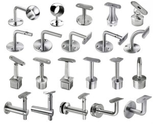
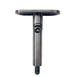
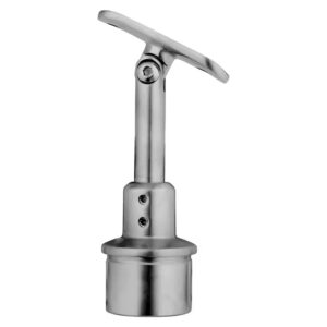
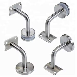
For concrete decks, surface mounting is the practical default in most conditions. Anchor edge distance is the controlling variable—anchors placed too close to a slab edge create splitting risk under lateral load, and that distance has to be confirmed against the anchor manufacturer’s requirements before the layout is finalized. Engineered anchorage solutions may create exceptions to the surface-mount default in specific structural conditions, but those require deliberate design input rather than field improvisation. Soportes para pasamanos de montaje superior designed for concrete and hard substrate applications are typically specified with anchor spacing and edge distance requirements that have to be incorporated into the layout drawing before drilling starts, not consulted after holes are already in the slab.
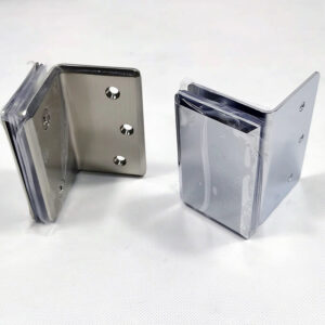
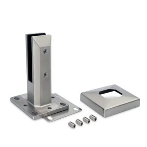
Where the structural backing, edge distance, and backside access questions cannot all be answered affirmatively for a fascia-mount layout, the mount type should change before the project commits further. Placas base para montaje en salpicadero suited to well-backed rim joist conditions represent a structurally appropriate choice when the framing verification is complete—but the hardware selection and the structural confirmation have to happen in that order.
Mount selection for railing posts is effectively a structural and waterproofing decision made under time pressure before the deck surface is complete. The factors that make one configuration appropriate—confirmed edge distance, verified backside access, coordinated framing layout, sequenced membrane detailing—are also the factors most likely to be discovered too late if the decision is deferred. For a more detailed examination of how load distribution differs between configurations in stair and balcony applications, Postes de acero inoxidable de montaje lateral frente a postes de montaje superior: Análisis de la distribución de cargas en escaleras y balcones addresses the structural mechanics behind each configuration.
Before finalizing a layout and proceeding to drill, confirm that the anchor substrate is structurally adequate and accessible for installation and verification, that membrane penetrations are accounted for with appropriate detailing where top-mount is selected, that fascia installation sequencing preserves access until hardware is fully tightened and signed off, and that post locations on fascia-mount layouts are tied into underlying framing rather than surface materials. Those confirmations are the gate. Everything else—bracket selection, finish, post spacing—follows from conditions that only become visible when those checks are completed first.
Preguntas frecuentes
Q: What can I do if my deck lacks the structural backing for fascia-mounting but I can’t puncture the waterproofing with top-mount posts?
A: Build a raised mounting curb on top of the deck that keeps post bases above the membrane. The curb is structural, anchored to the frame without piercing the main waterproof layer, and the railing then top-mounts to the curb. This solves the twin constraint—inadequate fascia structure and membrane sensitivity—by transferring loads through a dedicated elevation rather than through a surface or edge that both fail the design gate.
Q: After confirming that all anchor conditions are met, what documentation should I produce before closing up the work?
A: Produce a dated installation checklist with edge distance measurements, photos of structural backing (solid blocking, through-bolt engagement), and verification that all hardware is fully tightened. This record gives the inspector something to reference when the connection is later concealed behind fascia or under a finished surface, turning an unverifiable anchor into a defensible one.
Q: Is the waterproofing risk from top-mount penetrations still a concern if my deck sits at ground level with no occupied space below?
A: Yes, the concern shifts from interior leaks to concealed wood decay. Unsealed penetrations on a ground-level deck can still allow moisture to saturate framing members over time. Flashing and sealing each penetration remains the safer practice because the cost of replacing rotted rim joists or blocking far exceeds the cost of proper detailing at installation.
Q: Which mount type typically leads to lower long-term maintenance costs—top-mount with exposed base plates or side-mount with hidden anchors?
A: Top-mount posts tend to keep long-term maintenance costs lower. Base plates, bolts, and sealant remain visible and accessible, so loosening, corrosion, or sealant failure can be spotted during routine walks and corrected without disassembly. Side-mount hardware hidden behind fascia panels requires removing finished material for inspection, making neglected deterioration more likely and repairs more expensive.
Q: Is it worth using through-bolts and engineered hardware for fascia mounts on a small residential deck where codes may not explicitly demand it?
A: Yes. The incremental hardware cost is minimal compared to the liability of a guard failure. Through-bolts or engineered hardware provide a verifiable, inspectable connection that stays reliable over time, while lag screws alone are difficult to inspect once covered and are not considered adequate for life-safety loads in standard practice. In a small deck, the material saving is rarely worth the loss of a defensible load path.