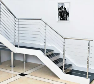
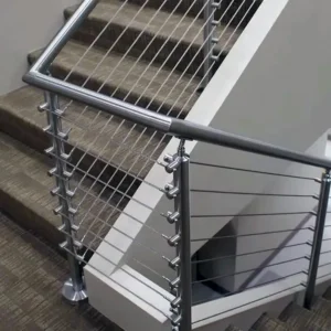
A post that passes a gripping-surface check in isolation can still fail an accessible route if the support beneath it, the landing it crosses, or the end condition it terminates in was never evaluated as part of the same run. The handrail-to-post detail is where continuity, clearance, and termination requirements converge, and getting it right depends on knowing which rules apply before the geometry is drawn.
Project Scope and Adopted Accessibility Criteria
| Project question | Evidence to review | Límite de decisión |
|---|---|---|
| Which accessibility rules govern? | The accessibility criteria and current adopted code identified for the project | Establishes the continuity, gripping-clearance, and extension provisions used for review; it does not by itself show that the post interface complies |
| What route condition is being evaluated? | Project drawings identifying the location and route condition of the handrail run | Determines where the adopted accessibility criteria apply to the run |
| What railing work is within project scope? | The project metal-railing specification, drawings, and construction scope | Establishes the required submittal scope; a guide specification is not a universal code or a product requirement |
Before any post, saddle, or bracket detail can be judged, the project team needs to establish which accessibility criteria govern the route in question. Accessibility requirements vary by facility type, occupancy, and jurisdiction, and the provisions that address stairway handrail continuity, gripping surface, clearance, and extensions depend on which code or guide has been adopted for the project. The Access Board Guide’s chapter on stairways addresses these continuity, gripping-surface, clearance, and extension provisions, but its applicability depends on the covered-facility context and the current adopted code for the project; confirming that scope is a prerequisite to evaluating any single post interface, not a substitute for it.
A second, separate question is which route condition is actually being reviewed. A handrail run through an interior stair differs from one at an exterior landing or a ramped transition, and the same adopted criteria may apply differently depending on where the run sits on the drawings. Where a project includes several distinct routes, each may need to be checked against the governing criteria independently, since a detail accepted on one run does not establish that an identical-looking detail on another run meets the same requirements. The project drawings identifying the location and route condition of each handrail run are the evidence that ties the adopted criteria to the specific geometry being reviewed.
The third scope question concerns what railing work is actually included in the project. A guide specification such as UFGS 05 52 00 Barandillas metálicas establishes a structure for metal railing specifications, submittals, drawings, and construction scope, but it is a guide-specification structure only, not a universal code and not a product requirement imposed by any manufacturer. What the project actually requires depends on the specification, drawings, and construction scope adopted for that project. Confirming this scope early determines what the submittal package must contain and prevents treating a generic specification template as if it were binding accessibility criteria. Once governing criteria, route condition, and railing scope are each confirmed, the post interface can be evaluated against a known standard rather than against assumption.
Continuity Through Posts, Landings, and Direction Changes
Handrail continuity is a property of the entire run, not of any single post or bracket considered on its own. A support that performs correctly in a straight run can still break continuity if it sits at a landing, a direction change, or a transition between flights without the run being evaluated as one system. The question is not whether an individual post detail looks acceptable, but whether the handrail remains functionally continuous as a hand moves from one segment of the route to the next.
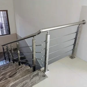
Landings and direction changes are where this distinction matters most. Where a stair or ramp changes direction, the handrail detail at that location has to resolve both the structural transition and the continuity requirement simultaneously; a bracket or post that is adequate mid-run may not resolve the same way at a corner or a landing because the geometry of the hand’s path changes there. Assuming that a standard bracket solution developed for a straight run will also solve a landing or direction-change condition skips the step that the drawings exist to answer. The project drawings have to be checked directly for how the run is detailed at each such location, because the same nominal hardware can produce a continuous or discontinuous result depending on where it sits.
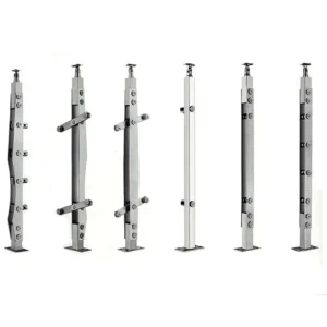
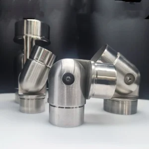
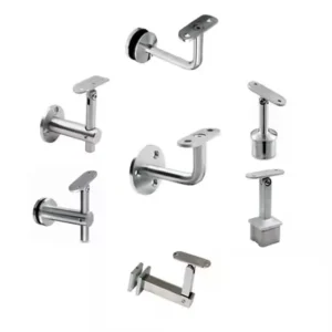
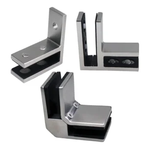
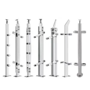
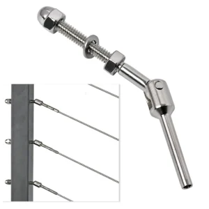
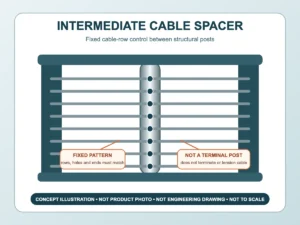
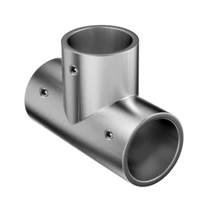
This has a direct consequence for how a buyer or reviewer reads a set of drawings. Rather than scanning for a single representative post condition and assuming it repeats correctly throughout, the reviewer needs to trace the run from one end to the other, noting every point where the route geometry changes and confirming that the continuity provision in the governing criteria is satisfied at each one. Where a run includes multiple landings or multiple direction changes, each one is a distinct condition to confirm, not a repetition of the first. This is also where intermediate post connectors become relevant, since the hardware connecting the rail to posts along the run has to maintain the same continuity logic at every post, not only at the ones shown in a typical detail.
Gripping Clearance Around Saddles and Brackets
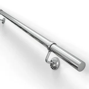
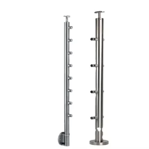
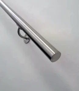
Gripping clearance is not a property of the handrail profile alone; it is a property of the complete interface formed by the post, the saddle or mounting plate, the bracket, and the rail together. A rail profile that meets gripping-surface requirements in cross-section can still fail the clearance requirement at the point where a bracket or saddle projects into the space the hand needs to wrap around the rail. Evaluating the rail profile by itself, separate from what supports it, misses the condition that most commonly compromises clearance: the support itself.
This is a geometric interaction, and it changes with the bracket’s position and projection relative to the rail. A saddle mounted directly beneath the rail has a different clearance effect than one offset to the side, and a bracket that projects toward the direction a hand travels interferes differently than one projecting away from it. Where the governing accessibility criteria specify a clearance zone around the gripping surface, that zone has to remain unobstructed through the bracket or saddle location, not just between brackets. A buyer evaluating a post-mount handrail system needs to confirm how the bracket or saddle is positioned relative to the rail at every post, because a detail that satisfies clearance at a typical post does not guarantee the same result where the bracket geometry differs, such as at a terminal post or a post carrying additional hardware.
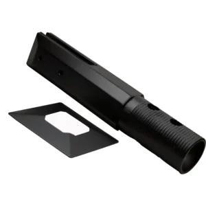
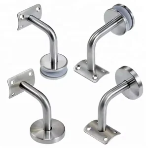
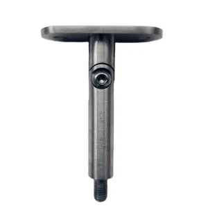
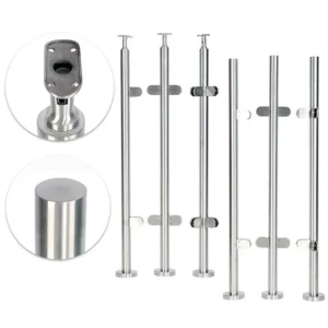
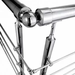
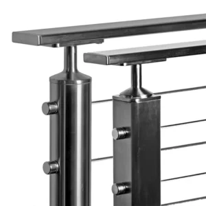
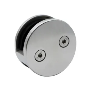
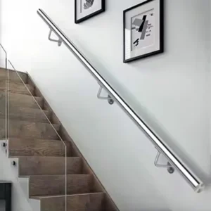
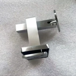
The practical implication is that the post, saddle, bracket, and rail should be treated as one interface when clearance is assessed, rather than as separate components each checked against its own requirement. A rail that is compliant in isolation and a bracket that is compliant in isolation do not necessarily produce a compliant assembly once combined, because the clearance requirement applies to the assembled condition. Where project drawings show the bracket or saddle detail only in a generic or schematic form, the reviewer needs the actual mounting geometry, including how far the saddle extends from the post and how it is oriented relative to the rail, before clearance can be confirmed. This is also the point at which product selection matters directly: the dimensional profile of the mounting hardware itself determines whether the assembled interface can meet the clearance requirement, which is a question the specific post-mount hardware and its connector details are meant to answer.
Terminal Returns, Extensions, and End Conditions
Where a handrail run ends, the end condition has to resolve both a safety function and a continuity function at the same time. A terminal return, an extension beyond the top or bottom of a stair or ramp run, or any other end condition is not simply a finishing detail; it is subject to the same adopted accessibility criteria that govern the rest of the run, and each type of end condition interacts with those criteria differently.
A terminal return addresses the projecting-hazard concern at the end of a rail by bringing the rail back toward the wall, post, or floor rather than leaving an open end projecting into the circulation path. An extension, by contrast, addresses the continuity and usability concern by carrying the gripping surface beyond the top or bottom of the stair or ramp so a hand has support before and after the change in level. These are distinct functions, and a detail that resolves one does not automatically resolve the other; a run could include an extension without a compliant return, or a return without the required extension length, depending on how the terminal post is detailed.
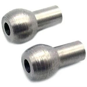
Where a project’s adopted criteria specify extension and return requirements, each end of each separate run has to be checked individually against those provisions, since the condition at the top of a run does not establish the condition at the bottom. This also includes any post-side projections at the terminal post, because a projection extending from the post itself, separate from the rail, can interact with the same hazard and clearance provisions as the rail’s own termination. The terminal post hardware used to form the return or extension has to be evaluated as part of this same geometry, since the hardware’s own dimensions determine whether the resolved end condition meets the extension length or return geometry the governing criteria require. Comparing the drawn end condition directly against the adopted criteria, rather than assuming a termination style is acceptable because it is common in similar projects, is the only way to confirm this before the detail is finalized.
Submittal Checks Before the Post Interface Is Approved
| Review item | What the submittal should show | Approval question |
|---|---|---|
| Governing basis | The adopted accessibility criteria and the route condition for the handrail run | Are the applicable review criteria identified before the detail is assessed? |
| Complete run geometry | Continuity through posts, landings, and changes in direction on the project drawings | Can the run be assessed as a continuous system rather than as isolated components? |
| Interfaz de publicación | The post, saddle, bracket, and rail together, including gripping clearance | Could a support interrupt hand clearance even if the rail profile is acceptable? |
| Projections and ends | Post-side projections, terminal returns, extensions, and other end conditions | Can each projection and end condition be checked against the adopted criteria? |
| Project scope | The applicable railing specification, drawings, submittals, and construction scope | Does the approval cover the project-specific assembly and scope shown? |
Approving a post interface requires evidence organized at the same scope as the questions the review has to answer, rather than a single drawing or product cut sheet asserting compliance. The governing basis has to be identified first, so that whoever reviews the submittal knows which accessibility criteria and which route condition apply to the run under review; a submittal that omits this leaves the reviewer unable to judge anything that follows.
From there, the submittal needs to demonstrate the run as a continuous system rather than as a collection of isolated components. This means showing continuity through every post, landing, and direction change on the actual project drawings, not a representative detail presented as standing in for the whole run. It also means showing the post interface itself, meaning the post, saddle, bracket, and rail together, so the reviewer can assess whether the assembled geometry preserves gripping clearance rather than assuming clearance from the rail profile alone.
Post-side projections, terminal returns, and extensions need to be documented as their own category of evidence, since these end conditions are evaluated against the governing criteria independently from the mid-run continuity and clearance questions. Finally, the submittal has to be tied to the applicable railing specification, drawings, and construction scope for the project, so the approval covers the assembly and scope actually shown rather than a generic or assumed condition. Where a buyer is sourcing the post-mount hardware, intermediate connectors, and terminal components for a project, the dimensional and configuration information submitted to the supplier for quotation and configuration review needs to match this same scope, since a supplier’s ability to match hardware to the project depends on the post spacing, saddle geometry, and end-condition details the buyer provides. Recording this evidence in one place lets the project team confirm the complete run before the post interface is approved, rather than approving individual components and discovering a continuity or clearance gap once the hardware is installed.
Preguntas frecuentes
P: Can an accessible handrail profile be approved before the post and bracket details are finalized?
A: No. Approval should cover the assembled post, saddle, bracket, and rail because a support or projection can reduce usable gripping clearance even when the rail profile itself appears acceptable. Finalize the interface geometry for each relevant location before approving the component combination.
P: When can one typical post connector detail be used throughout a handrail run?
A: Only when the project drawings show that the same detail remains applicable at the relevant posts and route conditions. Landings, direction changes, and end locations should be isolated for separate review when their geometry differs, rather than assumed to follow a straight-run detail.
P: Is an accessibility guide enough to establish whether a post-mounted handrail detail is acceptable?
A: No. Use the guide to understand the relevant continuity, clearance, and extension concepts, then confirm the accessibility criteria and current adopted code that govern the project and route. Project drawings and specifications must also establish where the criteria apply and what assembly is being approved.
P: How should intermediate and terminal handrail components be compared?
A: Compare them by their role and installed geometry at the actual location. An intermediate connection should be assessed for continuity and gripping clearance through the support, while a terminal arrangement should be assessed with its return, extension, projections, and other end conditions shown. A shared product-family label does not resolve those location-specific checks.
P: What information should be resolved before requesting approval of a repeated post detail?
A: Identify the governing criteria, route condition, and railing scope, then mark every place where the run changes direction, crosses a landing, or reaches an end. Confirm that the proposed repeated detail preserves the required review conditions at each marked location; submit a separate detail wherever the geometry or end condition changes.