Handrail continuity across stairs, ramps and landings depends on tracing one unbroken gripping line through every slope change and direction change before you select a single fitting or bracket. Where that line passes through a landing—turning, leveling or switching back—the geometry at the junction governs which connectors and support positions are even possible. The practical pressure on most projects is that stairs, ramps and landings are quoted in separate sections, and the joins between those sections are where continuity quietly disappears.
Map the Gripping Route Across Each Change
The whole job starts with one drawing that shows the gripping line as a single path, not as separate stair, ramp and landing products.
Draw that path on both plan and elevation. On the plan, mark every inside turn, switchback and direction change. On the elevation, mark every slope change, every support position and every true end of the rail—meaning a wall, an open edge or a code-required termination. At each of those marked points, note whether the route continues or ends. That distinction matters because a shipping break and a code termination look identical on a parts list but require completely different field details.
Related Products
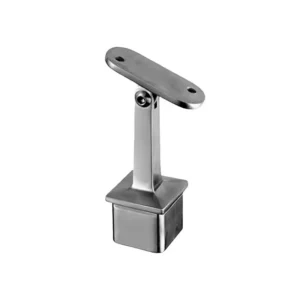
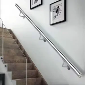
- Непрерывные настенные системы поручней — Review this candidate wall-support interface against the measured route and selected package details.
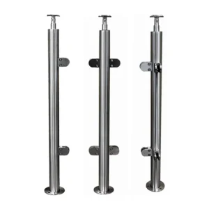
- Системы перил для круглых столбов — Review this candidate post-support interface against the measured route and selected package details.
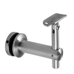
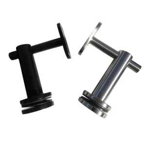
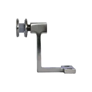
- Регулируемые кронштейны для настенных поручней — Review this candidate wall-support interface against the measured route and selected package details.
- Регулируемые поручни — Review this candidate post-support interface against the measured route and selected package details.
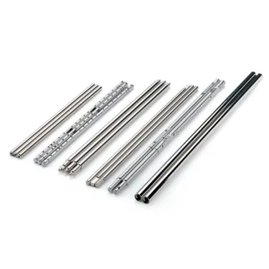
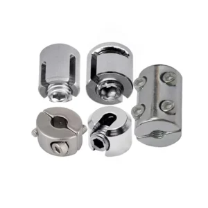
- Соединительные втулки для рельсов — Review this candidate joint interface against the measured route and selected package details.
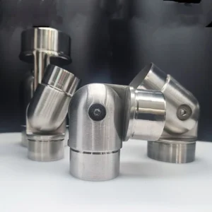
- Универсальные железнодорожные разъемы — Review this candidate joint interface against the measured route and selected package details.
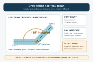
Slope changes и direction changes at landings deserve their own annotation. Where a sloping rail from a stair flight meets a level landing rail, the two centerlines arrive at different heights unless the transition geometry has been set. Where a ramp rail turns at an inside corner, the continuous gripping path must follow that turn without a gap the hand cannot bridge. Mark each of these conditions on the same drawing, in the same revision, before you divide the route into sections for quoting.
This shared route record does one specific thing that separate stair and ramp schedules cannot: it makes visible the places where independently quoted sections must physically meet. Without it, a specifier can approve a stair package and a ramp package that are each internally correct and geometrically incompatible at the landing.
Coordinate Stair and Ramp Geometry at Landings
Every landing is a geometry problem before it is a hardware problem.
Where a stair flight meets a landing, the sloping rail arrives at a rake angle and the landing rail is level. If you are working on a project within US accessibility scope, the Access Board’s stairway guidance addresses continuity through the flight and specifically at the inside of switchback or dogleg configurations. The inside of a switchback is the most demanding case: the rail must turn, and the gripping surface must remain reachable through that turn. The applicable provisions and how the authority having jurisdiction interprets them govern the final detail—that call stays with the project team—but the geometry check happens before fabrication, not after installation.
Stair Ramp and Landing Junction Checks
| Route location | Geometry to show | Connection check |
|---|---|---|
| Stair to level landing | Sloping and level rail in plan and elevation | Mating profile and junction elevation |
| Ramp inside turn | Run, landing and returning gripping path | Turn geometry and landing clearance |
| Landing to adjoining sloped rail | Both rail centerlines and the change of slope | Selected joint geometry at the shared end |
Ramps introduce the same class of problem across a longer run. Where a ramp run meets an intermediate landing, the sloping rail terminates or transitions and the landing creates a level break in the route. Inside turns on ramps, extensions at the top and bottom of runs, and the relationship between the rail position and the clear landing space are linked decisions. Set the geometry for all three before selecting connectors, because a fitting chosen for the nominal tube diameter may not accommodate the actual angle between a sloping and level centerline.
Plan view alone can hide a level mismatch between a sloping and level rail. Show adjoining centerlines, profile and joint geometry in elevation for every landing junction.
Consider a project where a stair flight, a level landing and a ramp run connect in a straight line on plan. On plan the layout looks clean. In elevation, the stair rail arrives at a rake, the landing rail sits level, and the ramp rail departs at a shallower pitch. At the stair-to-landing joint, the vertical offset between the sloping and level centerlines must be resolved by the connector or by a short curved transition. At the landing-to-ramp joint, the same question recurs at a different angle. Neither joint can be resolved from the plan alone, and a connector selected from a nominal tube-size match will not automatically fit either one.
The result of this coordination is a landing junction detail—elevation, profile and proposed joint geometry—for every slope change and direction change on the route.
Separate Supply Joints from Route Terminations
A rail route can include several kinds of joints, and treating them the same way produces errors in both directions.
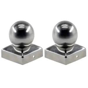
A true termination is where the gripping path ends: at a wall return, at a post at the edge of a platform, or at a code-required extension end. The rail stops here by design. The hardware at that end—a wall return fitting, a post cap, an end piece—reflects that the route does not continue.
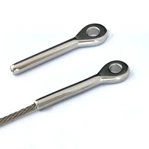
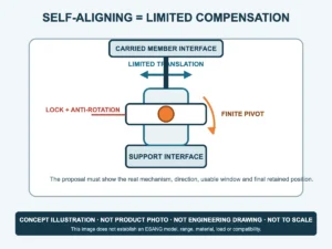
A supply joint is different. It is a location where one fabricated section meets another during installation to form one continuous installed rail. The mating ends at a supply joint must be detailed as mating ends—matching profiles, alignment provisions and connection hardware—not as two independent terminations. A shipping break driven by transport length or fabrication capacity may land anywhere along a continuing gripping path, and the installation detail at that location should show how the two ends join, how the alignment is confirmed and how the connection is made field-accessible or concealed, whichever the project requires.
Scheduling these two types separately prevents a common mistake: a location that is a supply joint appears on a parts list as two finished ends, the connection hardware is never specified, and the gap shows up at installation.
The practical step is to give every supply joint an explicit identifier in the schedule—a location reference tied to the coordinated drawing—and list both mating sections, the fitting or splice, and who performs the final connection. Where a project uses a shop-assembly and field-reassembly model, mark the reassembly points so the installer knows which joints were pre-fitted and which require field alignment.
Resolve Supports and Clearances Along the Route
The gripping line determines the route; supports determine whether you can install and use it.
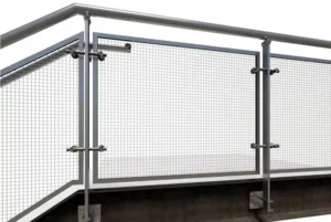
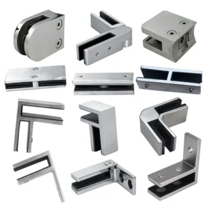
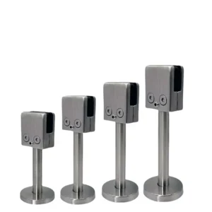
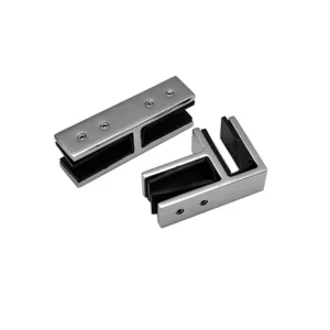
At each support position, the installed hardware occupies space beyond the rail centerline. A bracket arm, a post base plate or a glass clamp all project into the space the hand needs to clear the rail, the space an adjacent wall or structure must leave open, and sometimes the space a door swing or adjacent fixture controls. Checking the centerline is the starting point; checking the occupied envelope of each support is the field reality.
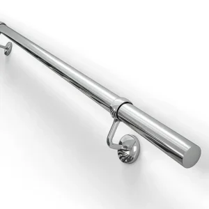
Wall-mounted bracket positions are set by the wall’s ability to take the fixing load at the required spacing and by the edge distance the substrate imposes. When the route passes a wall end, an open edge or a doorway, the last bracket before that transition must be positioned so the support itself does not reduce the gripping clearance below what the route requires. If the transition involves a bracket on one face and a post on another, the two support types arrive at the junction from different structural paths, and the connection access for both must be physically clearable in the installed condition.
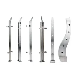
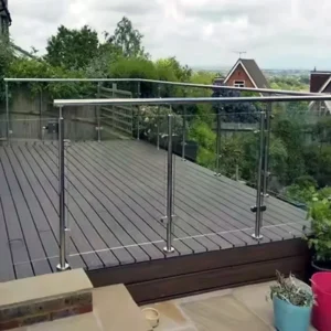
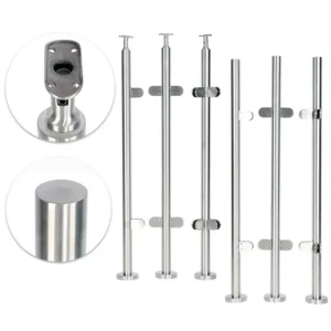
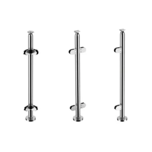
Post-mounted configurations carry a comparable set of questions. Where posts are spaced to suit structural loads, the spacing also controls how far apart the intermediate supports are along the route. At landings, posts may need to accommodate both the sloping rail from the stair or ramp and the level landing rail. That junction at the post—or just beyond it—requires a physical check of what fittings can be attached to that post at those angles, what the connection sequence is, and whether a bracket or clamp that handles one of the rail angles physically clears the other.
Where different trades supply adjoining route sections, give each junction one shared identifier and name the supplier of both mating ends and the connection work.
This matters at scope boundaries. If a structural contractor supplies a stair assembly and a railing subcontractor supplies the landing and ramp sections, the junction between those scopes is the highest-risk point for a missing connection. A single junction identifier—on the same drawing revision used by both suppliers—makes that interface visible as an item that must be supplied and installed, not as a residual detail that each party assumes the other has covered.
ESANG can configure post-mounted and wall-mounted hardware to suit the support positions and clearances that come out of this coordination, but the positions, substrate conditions and load requirements are project inputs that arrive from the structural drawings and the applicable engineering.
Related Reading
- Системы поручней для лестниц из нержавеющей стали: Выбор внутренних, наружных и непрерывных перил — Review the adjacent route-selection discussion before coordinating the package.
- Регулируемые кронштейны из нержавеющей стали для поручней на лестницах, пандусах и в условиях неровной поверхности — Check the bracket selection questions at changes in site geometry.
- Детали поручней из нержавеющей стали: Трубки, кронштейны, торцевые заглушки, стойки и соединители — Identify the components needed to turn the route drawing into a supply schedule.
Release One Coordinated Route Schedule
The schedule is what turns a traced route into a set of identifiable, ordered, installable pieces.
Build it from the coordinated drawing: one document, one revision, covering every section of rail, every support, every supply joint and every true termination along the route. Each entry carries a location reference, the section it belongs to, the support type or joint type at that location, and the supplier responsible for it. Supply joints carry both mating section references. True terminations carry the end-fitting detail. Sections that cross a slope change carry the elevation reference where the junction geometry was resolved.
This format makes route continuity a property of the schedule, not an assumption carried in someone’s head. When a section is missing from a delivery or a junction detail has not been confirmed, the gap appears in the schedule as an unfilled row, not as a problem discovered during installation.
Engineering loads, substrate capacities and applicable code criteria remain project responsibilities. ASTM E985 sets a boundary between what a railing system supplier can verify and what the installed-condition structural assessment requires. The schedule is the supplier’s deliverable; the structural and regulatory confirmation is the project team’s. ESANG’s fabrication scope is defined by the route schedule as released, and changes to support positions, substrate conditions or junction geometry after release require a schedule revision before fabrication proceeds.
Before releasing, have ready: the coordinated plan and elevation drawings with slope changes and direction changes marked; the landing junction geometry in elevation for each slope or direction change; the substrate type and fixing condition at each support position; the stainless-steel grade and finish specified for the exposure; and a clear notation of which joints are supply joints and which are true terminations. With those inputs confirmed against one drawing revision, the schedule can be released as a single coordinated package.
References
- Access Board Guide – Chapter 5: Stairways — Check the covered-US-stair continuity and inside-turn context before detailing a landing junction.
- Access Board Guide – Ramps and Curb Ramps — Check the corresponding ramp-run, inside-turn and landing-clearance context within US accessibility scope.
- UFGS 05 52 00 Металлические перила — Use the editable fabrication and assembly example to connect route drawings to delivered sections.
- ASTM E985-24 Permanent Metal Railing Systems and Rails for Buildings — Review the permanent-railing scope and field-condition boundary when separating package supply from project design.
Часто задаваемые вопросы
Вопрос: Can an identical staircase detail be reused at a ramp?
A: Reuse only the component information that actually matches. Check the ramp’s slope transition, landing and extension geometry separately rather than carrying over the whole staircase detail.
Вопрос: How should a later extension to the route be ordered?
A: Identify the existing mating end and the new drawing revision before ordering the added section. A new length should be tied to the actual continuation interface, not just the earlier rail profile.
Вопрос: What if a doorway is changed after the route package is released?
A: Trace the changed doorway to the affected support and rail junctions before altering components. Keep unaffected pieces identified, and reconsider the local occupied envelope with the revised door arrangement.