Most project teams commit to a clean glass balcony elevation before anyone has confirmed whether the slab edge can accept the fixing method, whether the glass thickness matches the anchorage capacity, or whether the drainage detail at the channel base will hold up after the first rainy season. Those gaps surface at engineering review, when the supplier redraws the entire package — a delay and cost that a polished rendering never suggested was possible. The practical risk is not choosing the wrong aesthetic; it is approving a system direction before the structural and fabrication conditions that gate every downstream decision have been checked. Working through this guide, you will be better positioned to sequence those checks in the right order and avoid the rework patterns that stem from locking a concept before the constraints are confirmed.
View preservation goals and the guard performance they limit
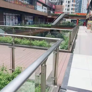
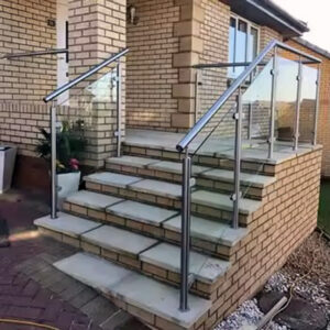
The first decision in any glass balcony railing project is not which system looks best — it is how much view continuity the guard performance requirements will actually allow once load paths, height, and infill geometry are set.
Full glass panels deliver continuous sightlines and eliminate fall-through gaps, but they also reduce natural airflow across the balcony face. Glass baluster arrangements can preserve some ventilation, but they reintroduce the fall-through risk that full panels eliminate. Neither choice is universally correct; the right answer depends on the occupancy, the orientation, and how the project team weighs unobstructed views against wind exposure and air movement at the balcony level.
What constrains that choice structurally are the IBC-referenced thresholds that most design teams use as planning baselines: 36 inches minimum height for residential occupancies, 42 inches for commercial, a 200-pound concentrated load capacity at the top rail, and post spacing no greater than 6 feet. These figures do not originate from a single universal mandate applicable in every jurisdiction without local verification — local codes and project-specific engineering must always be confirmed — but they function as the design envelope within which view area, panel width, and post layout must fit. A 42-inch guard with 6-foot post spacing leaves a defined glazing zone that cannot be expanded by preference alone. The panel dimensions, fixing locations, and structural demands that follow are all shaped by those numbers before a single hardware selection is made.
The downstream consequence of treating view goals as the primary driver — rather than one input within a constrained envelope — is that the system gets specified visually and then re-engineered structurally. That sequence is where most rework originates.
Fixing methods that change slab edge coordination
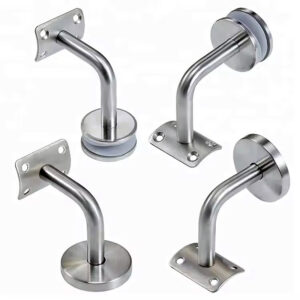
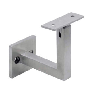
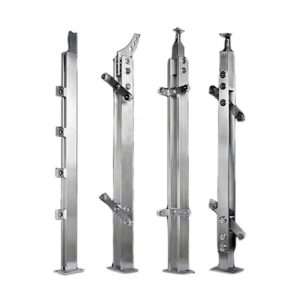
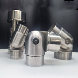
Fixing method is not a late-stage installation detail. It is a structural and coordination decision that must be made before slab edge profiling begins, because changing it after detailing is complete forces re-engineering of the edge condition, the anchor layout, and in some cases the concrete reinforcement itself.
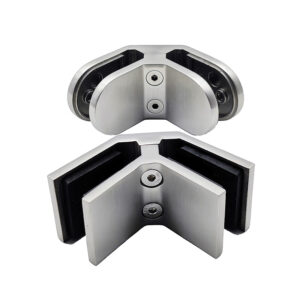
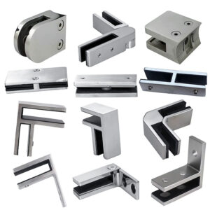
The core structural distinction between fascia mounting and deck mounting is load path. Beam sides and ends resist lateral load more reliably than slab top surfaces, which makes fascia-mount configurations generally stronger under the concentrated loads a railing guard must transfer. Deck-mount approaches are structurally simpler to install but more sensitive to slab surface variability — a common source of alignment problems in the field.
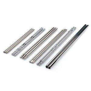
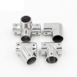
Base shoe channel systems add a layer of coordination demand regardless of whether they are fascia-mounted or surface-mounted. The continuous channel must be sized, positioned, and anchored in a way that aligns with the slab edge profile established by the structural drawings. If that coordination happens after the slab edge is cast or the formwork is stripped, the result is often shimming, grouting, or recutting that delays glazing and introduces new tolerance risk. Unitized systems with pre-drilled holes and pre-made cap rails reduce on-site adjustment by bringing that engineering precision to the factory, but they still require accurate field dimensions before fabrication begins.
Each fixing approach carries a different combination of structural strength, edge coordination demand, and rework exposure.
| Fixing Approach | Структурная прочность | Edge Coordination Demand | Rework Risk |
|---|---|---|---|
| Fascia mount (beam side/end) | Higher — beam sides/ends resist load | Requires precise slab‑edge profile alignment | Moderate — depends on field verification |
| Deck mount (slab surface) | Lower — relies on slab top surface | Simpler surface attachment | Higher — more sensitive to slab variations |
| Base shoe channel (fascia‑mount) | Strong continuous channel | Must coordinate slab‑edge profile early | Reduced if pre‑engineered channel used |
| Base shoe channel (surface‑mount) | Strong continuous channel | Surface‑mount detailing still needs early sign‑off | Reduced if pre‑engineered channel used |
| Unitized glass rail system | Engineered per project | Pre‑drilled and pre‑made cap rails simplify layout | Lowest — reduces on‑site adjustments |
The pattern that generates the most costly rework is approving a fixing method based on visual preference or supplier availability, then discovering at installation that the slab edge profile does not match the channel geometry or that the surface mount anchor layout conflicts with the reinforcement plan. Avoiding that outcome requires locking the fixing method in the design phase, not the procurement phase.
Tolerance errors that turn clean glazing into site rework
Custom glass panels are fabricated to fixed dimensions. Once the glass is cut, there is no field adjustment available that preserves the clean sightline — misaligned panels either get shimmed visibly, replaced at full cost, or held open pending re-order, all of which delay handover and generate callbacks.
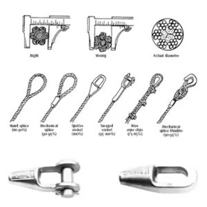
The practical fabrication threshold that most glazing contractors work to is measurement accuracy within one-quarter inch. That figure reflects field practice rather than a published regulatory dimension, but it is the tolerance window within which most panel fabrication tolerances and hardware clearances are designed to function. Exceed it in the field measurement phase and the glass arrives on site at the wrong size. The problem is not the number itself — it is the gap between that tolerance and the measurement discipline that many teams apply to what looks like a simple site dimension.
Dry glaze systems offer a meaningful mitigation path here. Because dry glaze relies on mechanical compression rather than sealant bonding, there is more capacity to adjust panel position during installation without committing to a permanent setting. That flexibility reduces the rework exposure when field dimensions deviate slightly from the fabricated dimensions — it does not eliminate the tolerance requirement, but it provides a correction window that wet glaze does not. Wet glaze systems fix the panel permanently once the sealant is applied, which means any dimensional error discovered after setting requires destructive removal.
The sequencing implication is that site measurements for custom glass panels should be taken after slab edge work and fixing hardware are installed and checked — not from drawings, not from nominal dimensions, and not before the slab edge condition is confirmed. Projects that measure from design drawings without field verification consistently produce panels that require adjustment or replacement.
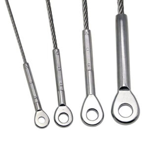
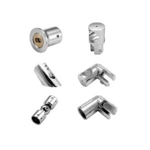
Spigot systems versus base shoes in fabrication and cost
The cost gap between spigot systems and base shoe systems is often invisible at the concept stage, when both options appear in the same rendering with the same clean glass look. It becomes visible at procurement, when the material specifications, fabrication tolerances, and drainage provisions are compared side by side.
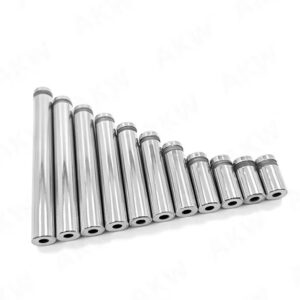
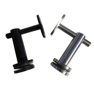
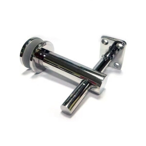
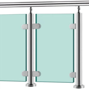
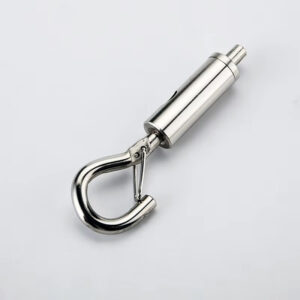
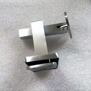
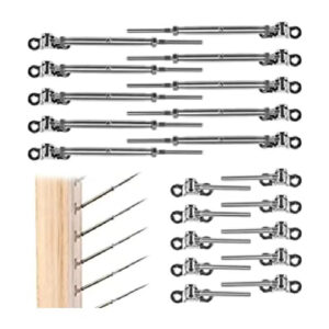
Стеклянные патрубки для поверхностного монтажа use 316 stainless steel and provide two-way fixing that allows precise panel-by-panel alignment adjustment at installation. That precision is an advantage on projects where slab edges have accumulated tolerance variation across a long run, because each spigot can be individually adjusted rather than forcing the entire panel layout to conform to a continuous channel baseline. The trade-off is material cost: marine-grade stainless steel carries a higher per-unit price than anodized aluminum, and the individual fixing points mean that alignment quality depends heavily on installation skill and sequencing.
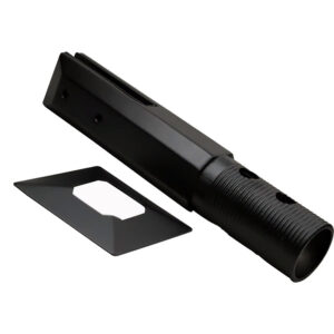
Направляющие для основания из структурного стекла in lightweight anodized aluminum provide a continuous channel with built-in drainage provision — a feature that matters significantly at the slab edge, addressed in the section that follows. The continuous channel generally delivers a cleaner sightline than discrete spigots because there is no visible hardware between panels at the base, which is often the aesthetic that buyers are trying to achieve. But that sightline comes at higher cost in channel fabrication, tighter installation tolerances along the full run, and greater sensitivity to the slab edge profile condition.
The structured comparison of materials, weight, corrosion resistance, drainage, alignment control, and cost sits across these two system types.
| Характеристика | Base Shoe System | Spigot System |
|---|---|---|
| Primary material | Lightweight anodized aluminum | нержавеющая сталь 316 |
| Typical weight | Нижний | Тяжелее |
| Устойчивость к коррозии | Good — anodized finish protects | Excellent — marine‑grade stainless |
| Drainage provision | Built‑in water drainage | Not integrated; separate drainage planning needed |
| Alignment control | Continuous channel; alignment depends on install precision | Two‑way fixing allows precise panel alignment |
| Стоимость материала | Typically more economical (aluminum) | Higher (stainless steel) |
The procurement mistake to avoid is selecting a system based on per-unit hardware cost without accounting for the installation labor, tolerance control requirements, and drainage provisions that each system demands. A base shoe system that costs more in hardware may deliver a lower total installed cost on a project with a clean, consistent slab edge and a controlled installation sequence. On a project with accumulated field variation, a spigot system’s per-panel adjustability may justify its higher material cost. Neither system is universally superior — the fit depends on site conditions, project environment, and the buyer’s tolerance for hardware visibility versus installation complexity.
Drainage details that protect anchors and finishes
Drainage is the detail most commonly deferred to the installation phase and the one most likely to generate callbacks after handover. Trapped water around slab edge anchors and continuous channels causes staining on glass and adjacent finishes, drives long-term corrosion at anchor embedment points, and degrades sealant joints that were specified to provide weather resistance — producing failures that often take one to two seasons to become visible and are expensive to remediate without disturbing the installed railing system.
The drainage method embedded in the system specification determines how well that risk is managed. Base shoe channel systems with built-in drainage are designed to move water away from the anchor zone, but that design intent only functions if the channel is installed with the correct slope, the drainage outlets are kept clear, and the slab surface below the channel does not pond water toward the anchor points. If any of those conditions is not met during installation, the built-in drainage provision fails silently — there is no visible indicator until staining or corrosion begins.
Glazing method interacts with drainage management in a way that is easy to underspecify. The table below captures how each approach distributes water management responsibility across the system.
| Water Management Method | System Context | Риск в случае неясности |
|---|---|---|
| Built‑in channel drainage | Base shoe systems | Moisture can become trapped around slab‑edge anchors, driving staining and long‑term corrosion |
| Sealant‑based wet glaze | Wet glaze systems | Permanent exterior weather resistance; failed sealants expose anchors to water ingress |
| Dry glaze (no sealant) | Dry glaze systems | Less suitable for wet conditions; higher chance of water reaching anchors and causing damage |
Wet glaze sealant-based systems are designed for permanent exterior weather resistance, but sealant is not a permanent material. UV exposure, thermal cycling, and movement at the glass-to-hardware interface eventually degrade sealant joints, and failed sealant creates a direct water path to the anchor embedment zone. Dry glaze systems avoid that sealant degradation mechanism but are generally less suited to consistently wet exposures, because the mechanical compression that holds the glass also creates pathways for water infiltration that sealant would otherwise block.
The practical confirmation to make before specification is whether the drainage outlet locations, channel slope, and slab edge geometry have been reviewed together — not independently. Projects that review each element in isolation frequently discover at installation that the outlet falls at a point where standing water is likely, or that the slab slope directs water toward rather than away from the anchor zone.
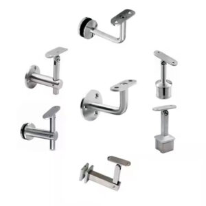
Cap rail decisions for code and user comfort
Cap rail selection is often treated as a finish decision made near the end of design, but it carries two distinct risks that appear earlier in the project than most buyers expect: a code compliance implication tied to height, and a warranty condition tied to material compatibility.
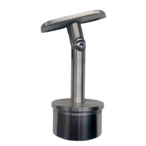
The 42-inch commercial guard height requirement, when met with a top rail positioned at that height, places the cap rail above the seated eyeline for most adults — a user-comfort outcome that aligns with the commercial code height rather than resulting from it. That distinction matters at the planning stage because buyers sometimes try to lower the cap rail for aesthetic reasons while retaining the guard height through a glass panel that extends above the rail. That approach requires engineering review to confirm the guard still meets structural performance requirements without the cap rail contributing to load distribution.
Material selection at the cap rail introduces a warranty risk that is less visible. Some manufacturers specify that adding a wood top rail to a glass railing system will void the product warranty, because wood’s thermal movement, moisture uptake, and surface hardness interact with the hardware connections in ways the system was not designed to accommodate. This is not a universal prohibition — it is a contractual condition that varies by supplier — but failing to confirm it before specification means the buyer may discover the warranty is voided only after the wood rail is installed and a callback event requires support. The check is straightforward: confirm cap rail material options and their warranty implications directly with the supplier before the material is specified, not after fabrication.
The second material consideration is corrosion compatibility. In coastal or high-humidity environments, a stainless steel cap rail paired with aluminum channel hardware without appropriate isolation introduces galvanic corrosion risk at the contact points. Coordinating cap rail material with the rest of the hardware specification — including fastener type and any isolation details — should be part of the same conversation as the warranty check.
Structural conditions that justify frameless glass
Frameless glass is the system direction that generates the widest gap between what buyers approve at concept stage and what the structure must actually deliver. The aesthetic case is easy to make; the structural case requires specific confirmation before the direction is viable.
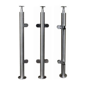
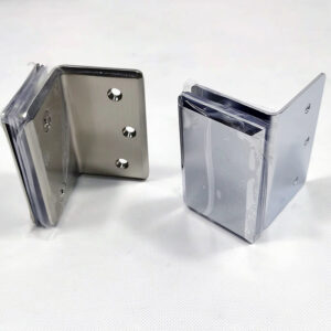
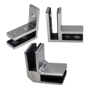
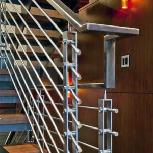
In a frameless clamp-style system, glass panels are held between posts without a top rail, which means the posts and slab edge must absorb the full lateral load without the structural contribution of a continuous top rail. That demands higher post embedment capacity, more robust slab edge reinforcement, and tighter deflection control than framed systems require. The building structure must be confirmed capable of absorbing those demands before frameless is specified — not after engineering review identifies the gap.
Wind load is the variable that most constrains frameless applications in elevated or exposed settings. As a design reference, frameless glass screen systems for rooftop applications have been installed up to 6 feet tall at elevations around 850 feet above ground, and up to 8 feet tall at elevations around 315 feet, under tested wind load conditions. These figures illustrate how the relationship between panel height and elevation affects wind load demand — they are not certified engineering limits applicable to all projects without local verification. A structural engineer must confirm the wind loads applicable to the specific site, height, and exposure category before these reference thresholds are used in any specification decision.
| Состояние | Threshold / Requirement | Что подтвердить |
|---|---|---|
| Wind‑load height limit (rooftop) | Up to 6 ft at 850 ft above ground; up to 8 ft at 315 ft above ground | Structural engineer verifies local wind loads for target height |
| Supporting post and slab strength | Frameless clamp style demands higher capacity from posts and slab edge | Post embedment and slab reinforcement can absorb increased moment |
| Deflection control | Structure must handle tighter deflection limits than framed systems | Hardware accuracy and acceptance of tighter movement tolerance are agreed before ordering |
The planning check that most teams defer too long is confirming hardware accuracy requirements and deflection tolerances before the frameless direction is approved. Frameless systems operate on tighter tolerances than framed systems because there is no top rail geometry to absorb minor misalignment between panels. When post embedment, slab edge flatness, and panel fabrication tolerances are not confirmed together, the result is visible misalignment between panels that requires hardware adjustment or replacement — a problem that is significantly more costly to correct in frameless systems than in framed ones. If the structure and the buyer cannot commit to the accuracy requirements before ordering, a framed or semi-frameless direction is usually the lower-risk specification. For projects where the structural conditions and accuracy commitments can be confirmed, reviewing the full glass balcony railing system options alongside the engineering constraints helps clarify which frameless configurations are feasible.
The sequencing logic running through every section of this guide points to the same practical implication: the decisions that look like finish or aesthetic choices — fixing method, glazing type, cap rail material, system style — are actually structural and procurement decisions that gate later work. Approving a system direction before confirming glass thickness, anchorage capacity, slab edge conditions, and drainage provisions does not defer those checks; it converts them into rework after the point where changes are cheap.
Before moving to supplier selection or fabrication, confirm that fixing method and post spacing are locked, that field measurements have been taken from the installed slab edge rather than from drawings, that drainage coordination has been reviewed against the actual slab geometry, and that cap rail material has been cleared against the supplier’s warranty conditions. If any of those items remains open, the supplier’s engineering review will surface it — the question is whether that happens before or after fabrication is underway. For guidance on what to verify when selecting the supplier who will carry this package through engineering and production, how to evaluate a stainless steel railing supplier before your first bulk order covers the qualification checks that reduce that exposure.
Часто задаваемые вопросы
Q: What happens if the slab edge is already cast before the fixing method is confirmed?
A: Expect re-engineering cost and schedule delay. Once the slab edge is cast, changing from a surface-mount to a fascia-mount configuration — or adjusting the channel anchor layout to avoid reinforcement conflicts — requires grouting, recutting, or adding supplemental structure that was not in the original budget. The fixing method must be locked before slab edge detailing begins because that decision determines the edge profile, anchor positions, and reinforcement demands. If the edge is already cast with no coordination for the railing system, a structural engineer needs to assess whether the existing condition can accept the intended fixing method before procurement moves forward.
Q: After locking the fixing method and taking field measurements, what should happen before sending an RFQ to the fabricator?
A: Drainage coordination should be reviewed against the actual slab geometry before the package goes out. Specifically, confirm that channel slope, drainage outlet locations, and slab surface drainage direction have been reviewed together — not independently. If the outlet falls where standing water is likely, or if the slab slopes toward the anchor zone rather than away from it, that condition needs to be resolved in the drawing package before fabrication begins. Sending an RFQ with unresolved drainage geometry means the supplier’s engineering review will surface the conflict after fabrication pricing is already committed.
Q: Does the advice in this guide apply equally to interior glass railings, such as inside a commercial lobby or stairwell?
A: The structural and tolerance logic applies, but the environmental risk profile changes significantly. Drainage provisions and glazing sealant durability are primary concerns for exterior balcony applications exposed to rain, UV, and thermal cycling. Interior installations are not subject to those moisture and weathering loads, which reduces the urgency of drainage coordination and sealant degradation checks. However, the fixing method sequencing, field measurement discipline, cap rail warranty verification, and frameless deflection control requirements remain equally relevant indoors — the guard performance thresholds and fabrication tolerances do not change based on exposure category.
Q: Is a spigot system always the lower-risk choice on projects with accumulated slab tolerance variation, or are there conditions where a base shoe still makes sense?
A: Spigots are lower risk on runs with significant accumulated variation because each panel can be individually adjusted without forcing the entire layout to conform to a continuous channel baseline. However, a base shoe system can still be the right choice on a project with high tolerance variation if the project team is willing to invest in a setting-out process that re-establishes a true reference line before channel installation — essentially correcting the slab variation at the installation stage rather than absorbing it through per-panel hardware adjustment. That approach requires more installation labor and planning precision upfront, but it delivers the cleaner continuous sightline that base shoes provide. The decision comes down to whether the project budget and schedule can support that setting-out rigor, or whether per-panel spigot adjustability is the more practical mitigation.
Q: At what point does the higher cost of a frameless system stop being justified by its aesthetic advantage?
A: When the structure cannot commit to the accuracy and deflection control requirements frameless systems demand, the cost premium is no longer justified — it becomes a budget exposure without a reliable outcome. The aesthetic case for frameless depends entirely on tight panel-to-panel alignment; if post embedment capacity, slab edge flatness, or panel fabrication tolerances cannot be confirmed and held within the tighter frameless threshold, visible misalignment will compromise the very appearance the premium was intended to achieve. On projects where the structural engineer cannot confirm adequate slab edge reinforcement and deflection limits before ordering, or where the buyer is not prepared to enforce the hardware accuracy requirements through installation, a semi-frameless or framed direction typically delivers a comparable visual result at lower total installed cost and reduced rework risk.