Before anyone sizes a railing post anchor, the concrete data for railing post anchors has to describe the element that actually receives the load: what the supporting element is (suspended slab, topping over structural slab, balcony cantilever, beam, curb or foundation), its verified thickness, whatever strength information exists, and the available structural drawings, all tied to the specific post locations. Those four items decide the anchorage depth you can use and the failure modes the designer must check, so a base-plate footprint and a post diameter on their own are not enough to proceed. Where the concrete is existing, repaired or hidden beneath a finish, add the measured edge geometry at each post and a dated record of its condition, because the design assumptions change with the real substrate rather than with the drawing of the railing.
Identify concrete properties and the supporting element
Start by naming the concrete element under each post and stating how you know what it is. A post landing on a 200 mm structural slab, a post landing on 50 mm of screed over that slab, and a post landing on a precast balcony with a thin topping are three different anchorage problems even though the base plate is identical. Anchor design depends on the concrete actually receiving the load, not on the surface the plate sits on, so the element type, its verified thickness and the depth of any non-structural finish all belong in the record from the start.
Strength information is the second property. Supply what the project has — the specified concrete grade from the original drawings, mix records, or any test data the owner holds — and state which of these is the basis. If a post location sits over concrete whose strength has never been established, say so plainly and mark it for investigation rather than carrying a guessed value into the calculation. The same applies to thickness: a dimension scaled from an old drawing is not a verified thickness, and the difference matters most where embedment depth is already tight.
Thickness governs more than it first appears. The usable embedment is bounded by the member depth less any cover and less whatever slab reinforcement or post-tensioning you must stay clear of, and shallow members change which concrete failure mode controls. Thin toppings, hollow-core units and composite decks each restrict the depth available, so identify the construction rather than treating every horizontal surface as solid concrete. Where the element is not known with confidence, record what is assumed and flag the assumption against the post location it affects.
Tie every property to a location, not to the project as a whole. A single verified core taken at mid-span tells the designer about that area; it does not describe the cantilever edge two bays away. Keeping the properties location-specific is what prevents one good measurement from being applied where it does not hold.
Dimension edges, openings and available fixing locations
Measure from the proposed anchor positions to every nearby free edge, opening and existing fixing, and record the distance to the concrete edge rather than the edge you can see. Anchors near a free edge develop less capacity than anchors in the field of a slab, and anchors placed close together interact, so these dimensions are part of the design input rather than a site detail resolved later. The geometry the connection review needs is the real one, which often differs from the tile, paver, coping or cladding line that defines the visible balcony.
That difference is the point worth checking carefully. A balcony finished with a tile overhang, a drip detail or an added nosing can read 40 mm wider than the structural slab beneath it, and a post positioned from the tile edge can end up with far less concrete behind the anchor than the drawing assumed. Where the concrete edge is concealed, say that the dimension is unverified and arrange to expose or probe it before the figure is used for design. A dimension taken from a finish and then treated as structural is the kind of error that only shows up when the hole is drilled.
Openings deserve the same treatment: drains, conduit sleeves, core holes, expansion joints and recessed channels all remove concrete from the zone the anchor relies on. Dimension them from the anchor positions in the same record. Existing fixings from previous railings, awnings or cladding count too, both because they occupy concrete and because old holes near a new anchor group change the local condition.
Finally, state how much room you have to move the post. If a post can shift 30 mm along the rail line without breaking the required opening limits or the rail geometry, say so, because that freedom is what lets the designer resolve an edge or reinforcement conflict without redesigning the assembly. Where the post location is fixed by a return, a stair stringer or an architectural setting-out, record that it is fixed; the connection then has to be solved within the geometry you measured.
Locate concealed construction and drilling restrictions
Supply whatever records exist for reinforcement, embedded services and prestressing in each supporting element, then state what investigation is planned and what drilling restrictions apply before the hole pattern is settled. Reinforcement layouts, post-tensioning tendon drawings, as-built service runs and any earlier survey all count, and so does the absence of them. An otherwise convenient base-plate hole pattern can fall directly on a tendon, a congested bar group or a conduit, so the available fixing positions have to be coordinated with the structure rather than chosen from the plate geometry alone.
Where records are incomplete or the element is post-tensioned, non-destructive scanning is the usual way to establish what is there before drilling. A clear scan is useful evidence, but it has to be read within its stated coverage: the depth it reached, the area it covered, the method used and the date. A scan that covered the top mat to a limited depth says nothing about a tendon below that depth, and a scan of one post position says nothing about the next. Record the coverage with the result so the designer and the installer are reading the same boundary.
Drilling restrictions belong in the same package. Projects commonly set rules on cutting reinforcement, on drilling in prestressed members, on maximum hole depths and on the method permitted near tendons. State the restrictions that apply, who imposed them and which locations they cover. Where a scan shows a conflict, the resolution — moving the post, moving the hole within the plate, changing the base detail or accepting a different anchorage approach — is a design decision made against the project’s approved procedure by its designated approver, not a field adjustment.
A practical habit helps here: mark the scanned obstruction positions on the same location drawing that carries the anchor positions. When both sit on one sheet, a conflict is visible before anyone sets up a drill, and the alternative hole patterns can be assessed while the base plate is still a drawing.
Provide the railing geometry and design demands
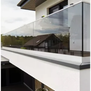
Issue the railing assembly as one coordinated set of design inputs: the project load criteria, the rail geometry, the infill type, the post arrangement and the base detail. The anchor demand comes from how the assembly collects and delivers load, not from a generic anchor size inferred from the post diameter. A guard loaded at the top rail produces a moment at the base that depends on the handrail height and the tributary length each post carries, and that moment is what converts into tension and shear at the individual anchors.
Each item changes the result in a specific way. Post spacing sets the tributary load per post, so a layout at wider centers raises the demand at every base even though the rail looks the same. Handrail height sets the lever arm for the base moment. Infill matters because a solid or glass panel collects area load that a cable or picket arrangement does not, and because panel infill can transfer load into the posts differently from an infill spanning rail to rail. The base detail — plate size, bolt pattern, whether the post is surface-mounted, side-mounted or cored in — fixes the distance between anchors and therefore the tension generated by a given moment, which is why a wider bolt pattern often reduces anchor demand without changing anything else. Where a surface-mounted base is still viable, the plate geometry is part of the input, because its hole positions determine the edge distances and spacings you measured.
Name the load criteria from the project rather than from a general assumption. For permanent metal railings in buildings, ASTM E985-24 covers permanent building guardrails, stair rails, ramp rails and handrails including basic design and load and deflection criteria, and it excludes ballasted systems and workplace occupancies governed by occupational-safety requirements; which criteria your project adopts is set by the project documents and the authority having jurisdiction. UFGS 05 52 00 Металлические перила is a useful illustration of how a railing specification and its submittals can be structured, as a guide specification written for project-specific editing rather than a universal requirement.
Label preliminary inputs as preliminary. A post spacing taken from an early elevation, an infill still under selection or a base plate not yet drawn can all be issued as working values, provided the designer knows they may move. The failure mode to avoid is a preliminary spacing quietly hardening into a fixed assumption after the anchors are sized. Once the geometry is settled, the verified concrete dimensions and the base-plate drawing package have to agree on hole positions, edge distances and tolerances, since that drawing is what the installer sets out from.
Package existing-condition evidence and unresolved inputs
| Input group | Information to include for the post location | Uncertainty to identify |
|---|---|---|
| Concrete properties and support | Supporting element type, verified thickness, strength information and available drawings | Properties that remain unverified and need investigation |
| Edges, openings and neighboring fixings | Dimensions from the proposed anchor locations to the actual concrete edges, openings and neighboring fixings | Concealed concrete edges that have not been verified beneath finishes |
| Concealed construction | Available reinforcement, service and prestressing records, planned investigation and drilling restrictions | Limits of the available records and scan coverage |
| Railing assembly and demands | Project load criteria, rail geometry, infill type, post arrangement and base detail | Inputs that remain preliminary |
| Existing concrete condition | Dated records locating cracks, repairs, deterioration and uncertain areas relative to the post bases | Local conditions requiring the project engineer’s investigation or testing decision |
Where the concrete is existing, repaired or showing distress, add a dated condition record that locates cracks, patches, spalling, corrosion staining, delamination and uncertain areas relative to the post bases. A design built from original drawings can be correct about the element and still wrong about the local condition at one balcony corner, because cracking, a previous repair or edge deterioration changes what that piece of concrete can do. The record should say where each feature is, how large it is, and how close it falls to a proposed anchor, with the date and who observed it. Which of those features requires further investigation, testing or remediation is determined by the project engineer; the installer’s job is to make the condition visible, not to assess it.
Assemble the whole submission as a schedule by location rather than as a single set of project-wide figures. Give each post base its own line with the concrete source and supporting element, the thickness and how it was verified, the strength basis, the edge and opening dimensions, the concealed items and scan coverage, the assembly demands, the condition observations and the items still unresolved. Distinguishing a balcony corner base from an interior landing base on the same schedule is what keeps one verified result from being applied where the conditions differ, and it makes every assumption visible to the person doing the calculation.
Treat the unresolved column as content, not as an admission. An entry such as thickness unverified, concrete edge concealed beneath tile, or scan limited to the top 80 mm tells the designer exactly which check must come before the anchor is fixed, and it lets investigation be scheduled once instead of discovered hole by hole. Issue the schedule with the structural drawings you have, the railing layout and base detail, the measured edge dimensions, the scan reports with their coverage stated, and the dated condition photographs keyed to the same post numbers. That package is what turns a railing layout into an anchorage that can be designed for the concrete it actually lands on.
Часто задаваемые вопросы
Вопрос: Can I choose the anchor size from the railing post diameter?
A: No. Post diameter alone does not define the anchor demand. Provide the project load criteria, rail geometry, infill, post spacing and base detail together with the concrete information so the connection designer can assess the assembly’s load path. Keep any early anchor selection provisional.
Вопрос: Can one set of concrete information cover every post on the project?
A: Only where its applicability to those locations has been verified. A balcony corner and an interior landing may have different edge geometry or supporting conditions. Identify which locations each record covers, and flag differences or unknowns before reusing a connection detail.
Вопрос: Are the original structural drawings enough for an existing concrete installation?
A: They are useful background, but they may not describe current local conditions. Add dated records of cracks, repairs, deterioration and uncertain areas relative to the proposed bases. Mark any unverified thickness or strength information for investigation; the project engineer determines what further investigation or testing is necessary.
Вопрос: Does a clear scan mean the proposed hole pattern is ready to drill?
A: A clear scan alone does not establish that. Check its stated coverage against the proposed anchor locations, available reinforcement, service and prestressing records, and the project’s drilling restrictions. Resolve uncovered or uncertain areas before treating the fixing positions as confirmed.