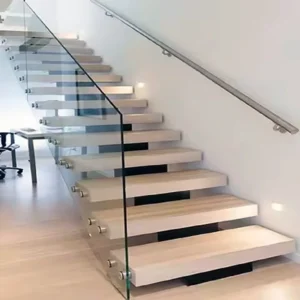
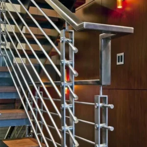
On a waterproofed balcony, the post anchor and the envelope are one detail, not two. Before you pick a surface, fascia, or core mount, map the membrane line, any upstands, the edge flashing, the drainage route, the structural edge, and the finished slope — because those six facts, not the mount label, decide where the fixing can land and what treatment the penetration or termination needs. Balcony railing waterproofing fails at the interface, so the deciding conditions are physical and measurable: where the membrane terminates, how thick the finish build-up is over the structural slab or steel edge, where water runs and where it leaves, and how far the anchor has to travel through finishes before it reaches something that can take guard loads.
Map the Balcony Waterproofing and Drainage Zones
Start by drawing the balcony edge in section, with every layer named, before any base plate appears on the drawing. You need the membrane and where it terminates, any upstands and how high they run, the edge flashing and its relationship to the membrane, the drainage route including outlets and overflows, the structural edge that will actually resist the railing loads, and the finished slope across the deck surface. Until those are on the same section, a mount choice is a guess about what the anchor passes through.
The reason to map drainage together with the membrane is that the two define different exposures at the same location. The membrane defines where a penetration becomes a water-entry point; the drainage route and finished slope define how much water arrives there and how long it stays. BRANZ guidance on problem decks makes the mechanism plain: fixings taken through a waterproof deck membrane create water-entry points, and poor drainage increases the chance of leakage at membrane joints or of damage to the membrane itself. That is a qualitative mechanism, and it applies to the ponding area and the flow path, not to a mount type in the abstract.
The structural edge deserves its own line on the section because it is often not where the finished edge is. A balcony may have a concrete slab edge, a steel edge beam, a nosing, or a thickened upstand, with insulation, screed, membrane, and a tile or paver finish above. The vertical distance from the finished surface to structural backup, and the horizontal distance from the free edge to sound material, are the two dimensions that most often close off a mount option before any aesthetic preference is considered.
Finished slope matters for a reason installers meet on site rather than on paper. A base plate set on a sloped deck sits on a plane that is not level, so the post needs either a packing or shimming arrangement or a base designed for the condition, and whatever you use sits in the wet zone. Fixing that geometry early is cheaper than discovering at post-setting that a level rail requires a wedge under one edge of every plate.
Compare Surface, Fascia, and Core Routes at the Edge
| Mount route | Attachment location to coordinate | Route-specific detail question |
|---|---|---|
| Placas de base para montagem em superfície | Balcony surface | How will the base coordinate with the finished slope, membrane, and structural backup? |
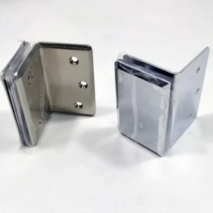
| Placas de base para montagem em fáscia | Fascia or side face | How will the side-mounted base coordinate with edge flashing, the drainage route, and structural backup? |
| Sistemas de base de montagem de núcleo | Core route at the balcony edge | How will the sleeve, grout, waterproofing treatment, and structural backup be defined? |
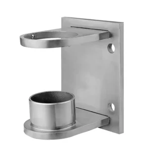
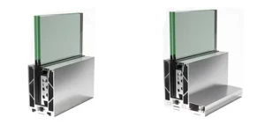
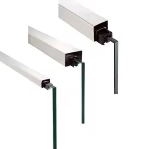
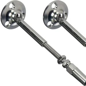
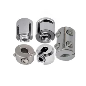
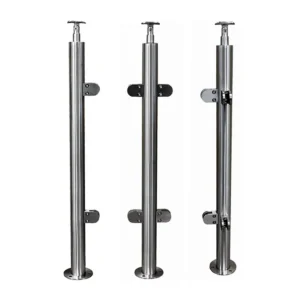
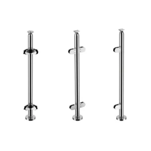
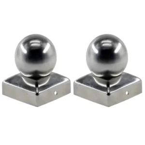
The three supported mount arrangements differ in one physical respect that drives everything else: where the load path crosses the weatherskin. A placa de base para montagem em superfície sits on top of the finished deck and sends its anchors down through the full finish build-up into structural backup, which means the fasteners cross the horizontal membrane in the area that collects water. A fascia mount base plate attaches to the side face of the balcony edge, so the fasteners enter a vertical surface. A sistema de base para fixação do núcleo sets the post into a cored or formed pocket at the edge, replacing discrete fasteners with a sleeve, grout, and a sealed termination around the post.
Those differences change the question you must answer, not whether you must answer one. BRANZ describes side-mounted barriers as placing fixings in a less risky part of the weatherskin than fixings driven through a deck membrane — a vertical face sheds rather than ponds. That reduces a described exposure; it does not remove the interface. A fascia-mounted base still needs the edge flashing, the membrane termination at the edge, and the drainage path past the fixing line all worked out, and it introduces edge distance and access constraints on the vertical face that a top-mounted plate does not have.
Moving the attachment therefore moves the envelope question rather than deleting it. A top-mounted base raises a penetration-through-the-deck question: how the plate sits against finished slope, how each fastener is sealed through membrane and finish, and whether the anchor reaches structural backup through the build-up. A side-mounted base raises a flashing-and-drainage question: how the base coordinates with edge flashing, whether fixings sit above or below the membrane termination, and where water passing the fixing line goes. A core mount raises a sleeve-and-grout question: sleeve type and depth, grout specification, the waterproofing treatment where the post passes the membrane, and whether the cored pocket keeps adequate edge distance in the structural edge.
As a starting position, where the balcony has a continuous horizontal membrane and a drainage route across the deck, a side or core arrangement is worth examining first precisely because it keeps fasteners out of the ponding plane — but the deciding facts are the edge’s structural depth, available edge distance, and whether the fascia or edge construction can take guard loads at all. If the structural edge is shallow, obstructed by an upstand, or unable to accept a side fixing, a surface mount with a fully detailed penetration treatment is the honest answer, and the detail then carries the sealing burden.
Trace Each Anchor Through Finishes to Structural Backup
| Detail checkpoint | Project entry to show | What the entry makes reviewable |
|---|---|---|
| Mount arrangement | Selected surface, fascia, or core route and the dimensioned post and base requirements | The starting geometry for product and interface coordination |
| Penetration or termination | Each location where the mount creates a penetration or termination | The exact points that need a selected treatment |
| Interface treatment | Selected treatment at each identified penetration or termination | How the waterproofing interface is intended to be handled |
| Structural backup | Anchor path through the finishes to the structural backup | Whether the substrate interface is included in the detail |
| Waterproofing sequence | Any dependency between anchor work and waterproofing work | Whether the drawing captures the required work sequence |
| Inspection access | Access provided for the identified interface points | Whether the selected treatment remains available for inspection |
Every anchor on the drawing should be traceable from the base plate or sleeve, through each finish layer by name, to the structural element that resists the load. The trace is what converts a mount preference into a buildable detail, because it forces the three facts that get assumed: how deep the anchor must be to engage structural backup, which layers it passes through, and what happens at each layer it breaches.
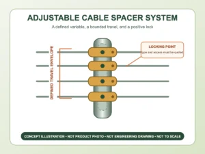
Record each location where the chosen arrangement creates a penetration or a termination, and give each one a selected treatment. A penetration is a fastener or sleeve passing through the membrane; a termination is where the membrane stops and is sealed against another element, such as an upstand, a flashing, or a post sleeve. Treating those as separate entries matters because they usually belong to different trades and different materials, and a detail that names one without the other leaves the site to improvise.
Sequence is part of the trace. Some arrangements require the anchor or sleeve to be set before the membrane is applied and dressed into it; others require the membrane to be complete and cured before anything is drilled. Writing the dependency into the detail is the only way to prevent a post being set into a surface that a later trade then has to patch. ASTM E985-24 gives basic minimum design and load and deflection criteria for permanent metal building railings, but it is explicit that design for specific field conditions remains the responsibility of the designer, specification writer, and code agencies — so the anchor trace through a particular balcony build-up is project design work, not something a railing standard settles.
Inspection access belongs in the same trace. If the selected treatment at a penetration will be buried under a paver, a deck board, or a finish that cannot be lifted, say so in the detail and decide whether that is acceptable before release. Core-drilled posts carry this concern most sharply, since the sleeve, grout, and waterproofing termination sit at the one point you cannot open later without disturbing the post.
Coordinate Flashing, Sealant, Slope, and Inspection Access
These four coordinate as a set because each one fails differently when the others are decided in isolation. Flashing establishes the primary geometry that sheds water away from the fixing line; sealant is a secondary line that depends on joint geometry, substrate preparation, and compatibility with the membrane material; slope determines whether water is moving past the detail or standing on it; access determines whether anyone will ever see the detail again.
The practical rule is that sealant should not be asked to do the job of flashing or slope. A bead around a base plate on a flat or back-falling surface is holding back standing water; the same bead above a correctly flashed, free-draining fixing line is a secondary defense. Where the section shows the fixing line sitting in the flow path or in a low spot, the correction belongs in the flashing and slope, not in a larger sealant joint.
Compatibility is a specification question rather than a site question. Membrane systems are chemically specific, and the sealant, the sleeve material, and any grout at a core mount have to be acceptable to the membrane manufacturer and to the envelope specialist on the project. Where the membrane is already selected, that information exists; where it is not, the single missing variable is the membrane system itself, and the envelope specialist or project designer holds it.
Access planning also covers protection during the rest of the build. NHBC’s best practice guidance on balconies joins fixing back to the main frame with weatherproofing across the balcony footprint, tray-to-membrane interfaces, and drainage and overflow maintenance, and it raises protecting membranes from damage by later trades — that guidance is written for UK registered-builder award purposes and is not a technical specification, but as a planning reminder it is directly relevant: the post anchor detail is often installed in a zone that subsequent trades will walk, load, and store material on.
Bring Railing and Envelope Inputs Into One Detail Review
| Revisar os dados inseridos | Route or confirming party | Limite de decisão |
|---|---|---|
| Dimensioned post and base requirements | Provide to ESANG for the selected mount review | Supports post and base coordination; it does not confirm the complete balcony-edge assembly |
| Membrane, upstands, flashing, drainage route, structural edge, and finished slope | Project designer and envelope specialist confirm the complete assembly | Establishes the project-specific envelope and edge context for the mount detail |
| Field-specific railing design criteria | Project designer, specification writer, and code authority retain responsibility | ASTM E985 provides railing design criteria but does not replace the project-specific determination |
| Project-specific railing specifications, submittals, and drawings | Use the project’s own review documents | UFGS 05 52 00 is a specification-structure example, not a universal code or an ESANG product requirement |
The balcony-edge mount detail should be reviewed once, with the railing inputs and the envelope inputs in front of the same people, rather than approved twice in sequence by parties who each see half the section. The reason is that each side holds a constraint the other cannot resolve: the railing side fixes post spacing, base footprint, bolt pattern, and the load the anchor must carry, while the envelope side fixes membrane type, termination heights, flashing geometry, slope, and drainage.
What ESANG can usefully receive at this stage is the dimensioned post and base requirement — post size and spacing, base plate or sleeve geometry, fixing pattern, stainless grade and finish for the exposure — so the hardware matches the mount arrangement the project has chosen. Confirming the complete balcony-edge assembly, including whether the selected treatment at each penetration or termination is acceptable, sits with the project designer and the envelope specialist.
Keep the standards and reference documents in their stated roles during that review. ASTM E985 supplies railing design and load and deflection criteria for permanent metal building railings and expressly leaves field-condition design with the designer, specification writer, and code agencies. A project railing specification, whether the project writes its own or works from a published specification structure, organizes submittals and drawings; it is not a substitute for the project’s own approved documents, and none of these sources establishes a waterproofing approval or a performance rating for a particular assembly.
Release the Mount Detail After Both Interfaces Are Confirmed
Hold the mount detail until the structural interface and the waterproofing interface are both confirmed, because releasing on one of them is what produces posts that stand up correctly and leak, or details that seal correctly and lack anchorage. The release itself is a project decision: whatever approved procedure governs detail issue on the job, and whoever that procedure names as approver, makes it.
Before that review, have the balcony edge section drawn with membrane, upstands, flashing, drainage outlets and overflows, structural edge and finished slope shown; the selected mount arrangement with dimensioned post spacing, base geometry, and fixing pattern; each penetration or termination identified with its proposed treatment; the anchor depth and path through the finish build-up to structural backup; any sequence dependency between the anchor work and the waterproofing work; the specified stainless grade and finish for the exposure; and a note on what inspection access remains once the finish is complete. A detail carrying all of that can be checked against the real balcony; one missing the structural depth or the membrane system can only be checked against intentions.
Perguntas frequentes
P: Does moving the post from the balcony surface to the fascia avoid waterproofing coordination?
A: No. A fascia mount changes where the interface occurs, but the detail still needs to show how the base relates to edge flashing, the drainage route, and structural backup. Compare that side-face condition with the surface route through the finished slope and membrane before choosing between them.
P: When should a mount route remain unresolved instead of being released for detailing?
A: Keep it unresolved when the project cannot yet trace the attachment to structural backup, define the treatment at each penetration or termination, or preserve review access. The missing item should be resolved against the actual balcony-edge build-up rather than assumed from the mount label alone.
P: What information should accompany a railing-post mount request?
A: Provide the selected surface, fascia, or core route; dimensioned post and base requirements; and the project-specific edge assembly showing the membrane, upstands, flashing, drainage route, structural edge, and finished slope. Also identify the proposed treatment at each penetration or termination so the product and envelope interfaces can be reviewed together.
P: How should installation sequencing affect the mount decision?
A: Identify any dependency between the anchor work and waterproofing work before releasing the detail. If the planned sequence would conceal an interface before its treatment can be checked, revise the sequence or access provision while the mount arrangement is still being coordinated.
P: Who confirms that the complete balcony-edge detail is acceptable?
A: ESANG can review the dimensioned post and base requirements for the selected mount, while the project designer and envelope specialist confirm the complete balcony-edge assembly. Field-specific railing criteria and project documents remain with the project designer, specification writer, and code authority; a product review does not replace those project decisions.